All Activity
- Past hour
-
 We use Shaded render for a lot of our work. When we present interior spaces the ceilings always appear too dark. I assume that Shaded (like Open GL) can support up to eight light sources. What's a simple way to use Shaded, but get the ceilings brighter, and evenly illuminated? Thanks, Ed
 -
I don’t know if this is a recent change in the licensing for Twinmotion, but their website now says the following: I don’t recall it being free for companies with less than $1 million USD annual gross revenue.
-

Who has need for Live Sync with both Blender and D5 Render?
twk replied to MattWhite's question in Wishlist - Feature and Content Requests
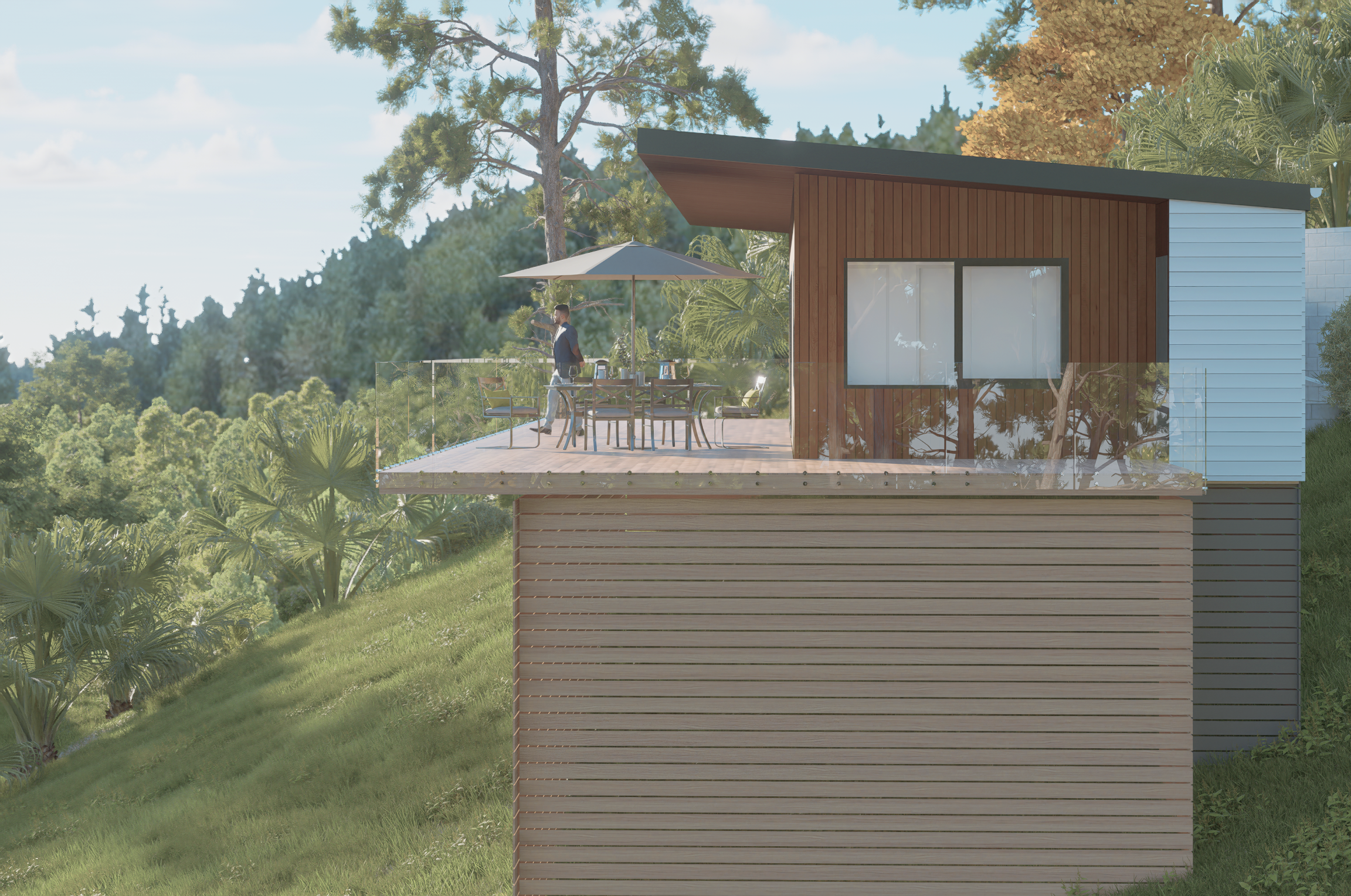
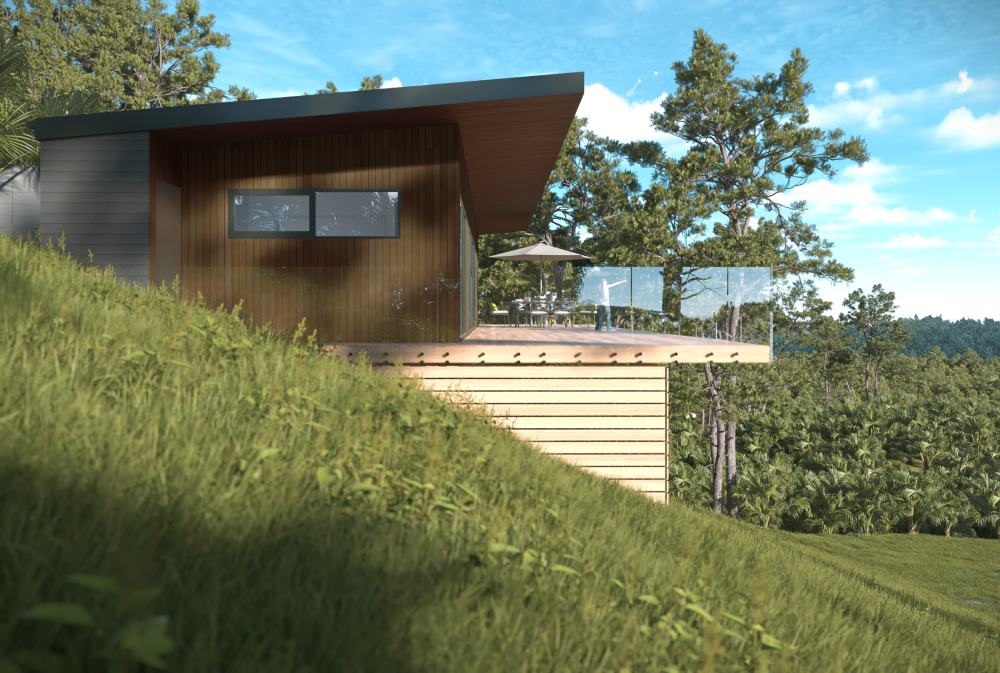
Have been testing D5 render past couple of days, and I must say its new scatter tool is very impressive, managed to fill a forest and no noticeable lag, as in Lumion/Twinmotion (even with their culling capabilities). Some caveats: - needs a decent graphics card (I'm on an RTX 3060Ti), website says RTX, or any of Nvidias DirectX Ray Tracing (DXR) graphics cards - and yes, only Windows - some exports of DTMs translate over as flipped normals making the grass/nature elements scatter on the wrong side of the mesh. Only noticed with converting old VW versions to 2024. The fix is to regenerate the DTM (copying out site data, and recreating Site Model) ++Pluses: - A lot of ready to use high quality 3D assets/trees - Fast render times in my testings (images below took about 1m30sec each for 4k) - A good number of example scenes to work with - Pricing is very competitive compared to Lumion and Enscape, can't beat Twinmotion though, as thats FREE now. --Minuses: - needs a good (read expensive) graphics card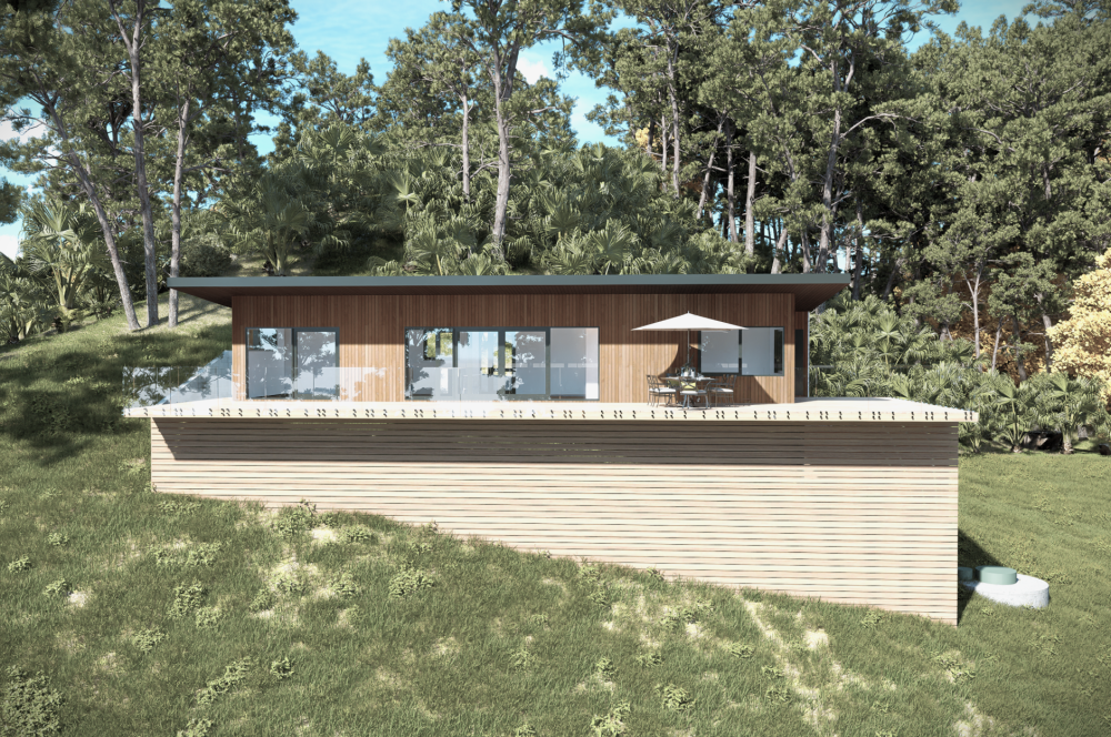

-
Thanks @Jeff Prince. I've not tried outdoors yet, but will adopt that up / down technique. I also do a kind of spray technique indoors in the smooth circular motion as per the instructions on Nomad. In that stairwell scan I think I did accidentally make a more sudden shift and that might explain the superimposed plans - there is quite a technique to this it seems... What is your experience with this fuzz / poche effect that was my original query though? It definitely seems to be the case that this is applied mass / material behind the scanned surface. I have just been playing around with this some more and there is also a technique to interpreting scans in VW it seems - little tilts into 3D every now and then so you can check up that you are correctly tracing the wall surface. This does indicate that the room facing points show the surface and then this is given mass by density of points behind them. I'm intrigued by this as it suggests that these "mass points" are not therefore scanned points, but added points (behind the scanned plane) to aid the legibility of the outputs. But that's just a guess. This technology is very mysterious and I must admit that this scattering dust and seeing it taking shape into the room does seem a bit like magic! I also just discovered the automated points reduction edit in VW - makes the rather ropey scans I am working on much clearer.
-

Object Info - Render Tab missing options on Wall Tool
Cody Worthman replied to Henry_SRL's topic in Site Design
The wall your coworker has selected isn’t the same wall style as selected in your file, is it? I can’t tell you why you’re not seeing the same by face/by object options, but try editing the wall style, going to the texture tab, and select the same texture for each part, or set the overall texture then select each part and revert to overall.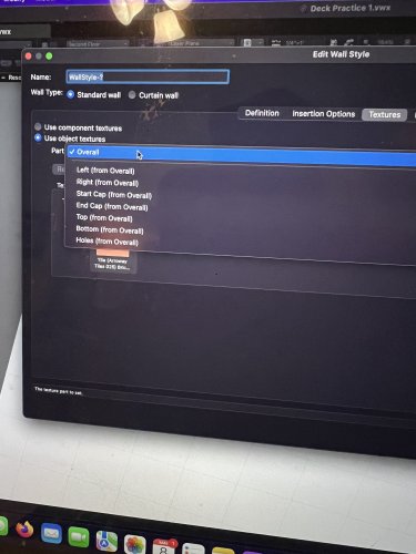
-
Once you make the opening how do you get the edges of the walls to appear as gypsum board? I checked both uploaded files and cannot figure this out. Thanks!
-

Multi-column Layout
Jesse Cogswell replied to NealP's question in Wishlist - Feature and Content Requests
Good morning, friends. I made some adjustments to this plug-in based on feedback from @BartHays. The changes are as follows: When Multi-Column is selected and Text Box children are created, their position will initially be locked to the parent Text Box, matching the top of the Text Box and spaced using the Column Spacing parameter. When locked in such a matter, moving the parent will also move its downstream children. This can be turned off by unchecking the Lock Position to Parent checkbox in the Object Info Palette. When you are using bulleted or numbered lists, Bart noticed that if a box was split in the middle of a listed item, it would start a new item in the next Text Box, eeven if it wasn't supposed to. I couldn't find a way to automatically detect if the split was in the middle of a listed item versus between listed items, so I just added an Override List at Start checkbox in the Object Info Palette, which will override the listing rules for the very beginning of the Text Box. This will only appear if the split was in the middle of a list. Speaking of listed items, in the original object, all listed lines would be automatically tabbed in. This looks fine for text boxes justified left, but looks goofy for any other justification. There is now a checkbox in the OIP called Tab in List Formatting. Unchecking this option will not tab in for listed lines. Installation instructions are the same as listed above. If you already have the object installed, following the instructions above should write over the original object. Let me know if you experience any trauma. JNC-Text Box.zip - Today
-
I was going to say the same a @Katarina Ollikainen. You can set a different epsg/coordinate system for the design layer you are using for your geoimage. It should be a different layer then your other geometry. I am not familiar with those coordinate systems, or how this process works in terms of transforming between a national coordinate system and a universal coordinate system like UTM. A national coordinate system will obviously give you different locations for the same coordinate values. I have used this before for different coordinate systems, where the main difference between the epsg codes related to updated height info, not different x/y. It can also depend on what coordinate systems the data provider has used. If it hasn't listed one of the codes you are using, your will probably get problems.... Or it won't work at all in many cases. The HSY site says that it is provided in EPSG 3879, and not EPSG 3067... So I don't think you can expect the WFS/WMS to work. You may be able to use the geolocated image, explode that and then import/transform that image into another file with the different coordinate system...

-
Write Excel data to Lighting Device
Jesse Cogswell replied to Company Call BV's topic in Entertainment
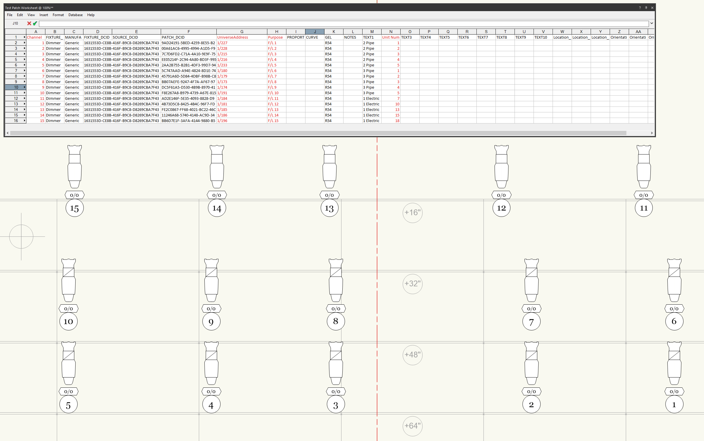
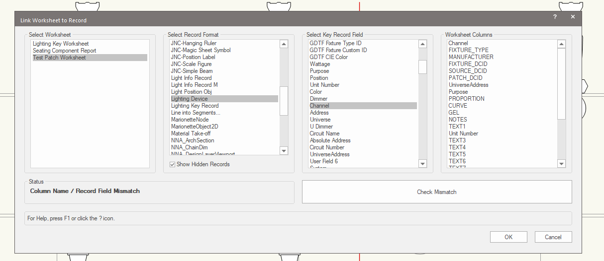
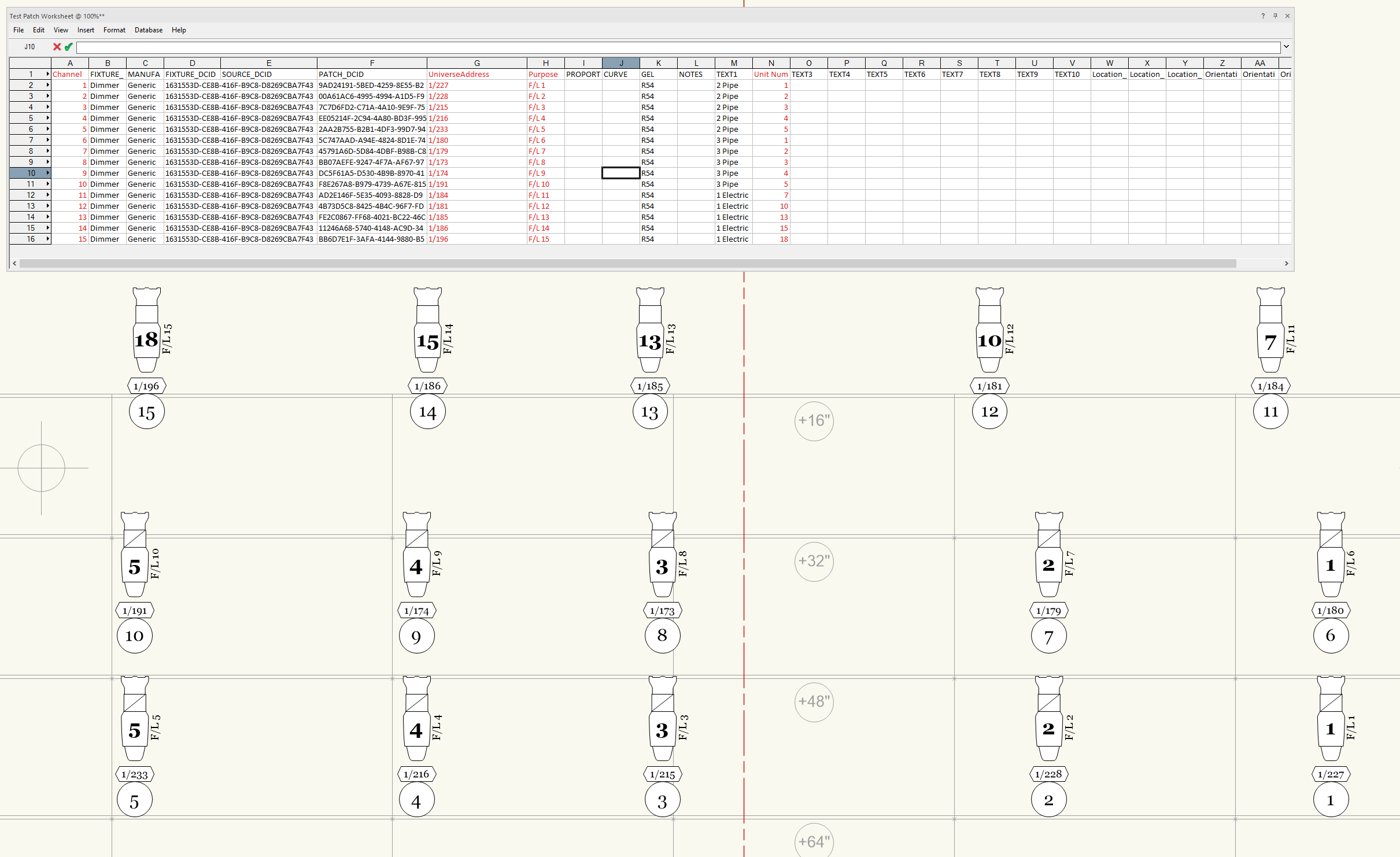
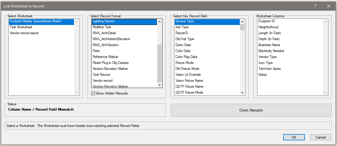
I wrote a script that can link a worksheet (including a referenced Excel document) to a record format, as detailed in this post: I have since added a feature to allow the user to select the record behind parametric objects such as Lighting Devices, download link can be found here: @Company Call BV Here's why this is relevant to you: you should be able to use this command to link an imported worksheet with patch data to the Lighting Device record to patch your fixtures. I ran a quick test by exporting a .csv from an Eos show file and used it to patch some fixtures. The key here is that the top row of the worksheet must be column headers and must match the parameters of the Lighting Device object (easily found by going to File - Document Settings - Spotlight Preferences and selecting the Lighting Devices: Parameters tab). Example patch worksheet and fixtures. Columns to sync are colored red: Selecting the proper options in the Link Worksheet to Record dialog box: In this example, I used the Channel field as the key. With this plug-in, this process will only really work if you have a single fixture per channel, otherwise it will very likely make all matching channels match whatever is the lowest matching row in the worksheet. In this instance, I would very much recommend not clicking the Check Mismatch button, since it will list out all of the parameters of the Lighting Device object not found in the worksheet (which is very likely a lot of them). Result from running the command: Give this a shot and see if you can make it work for your use case.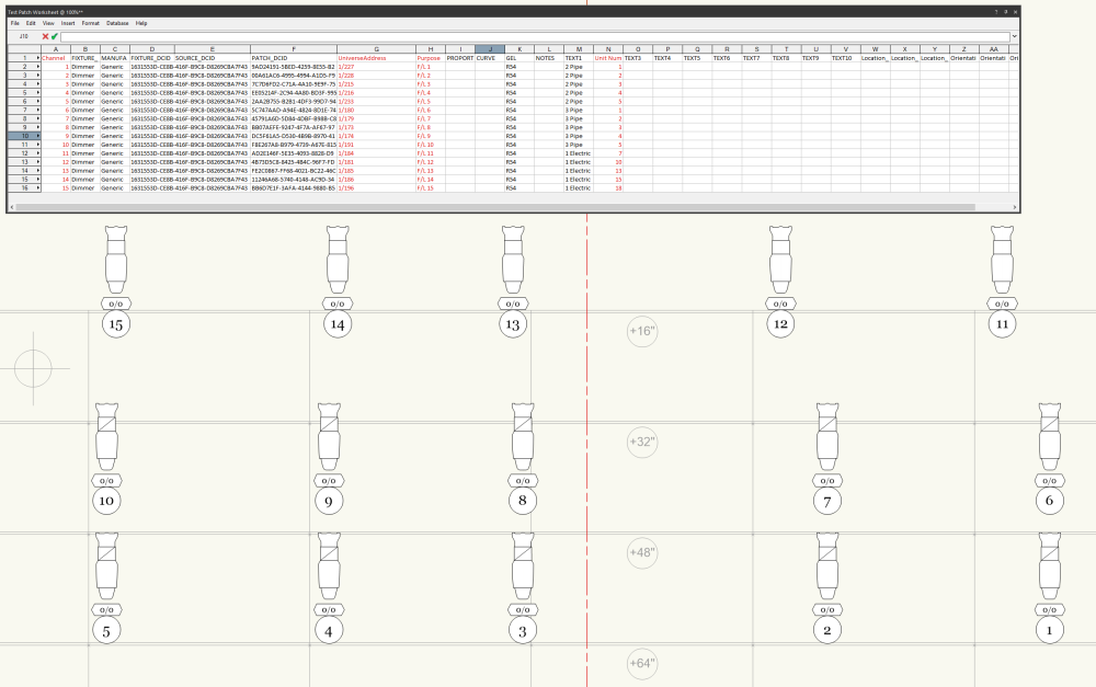


-
I'm getting the same problem. An extra line, the depth of the wall, only with doors that have a sidelite on one side and not the other. The errant line appears where the jamb would be if there was an identical sidelite on the other side. Also, in 3D the door resize handles are shifted. Vectorworks 2024, Sonoma, latest version. I see the fix for this is addressed in the next update. When is that out? Thanks
-
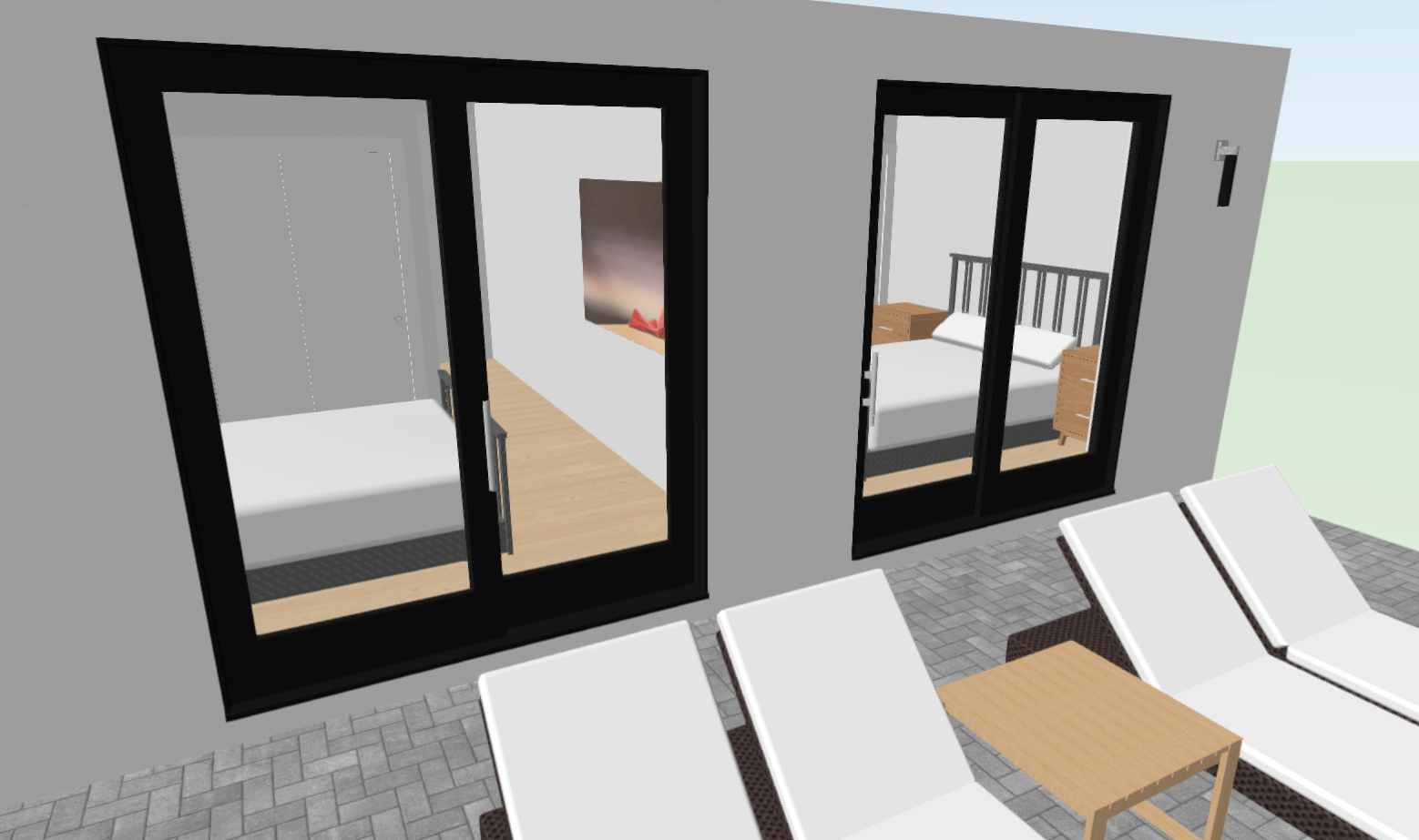
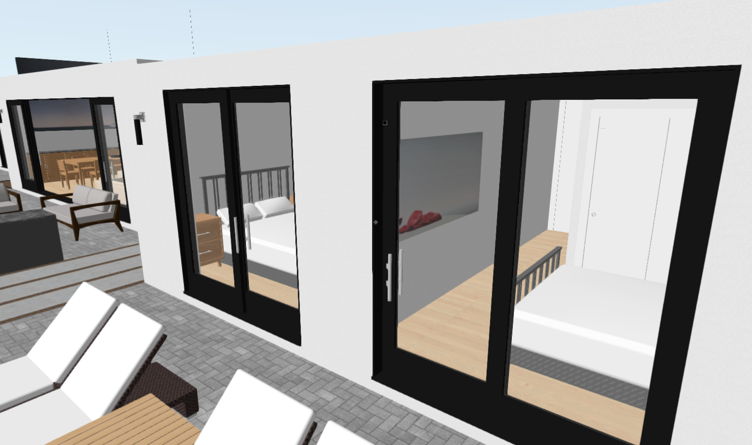
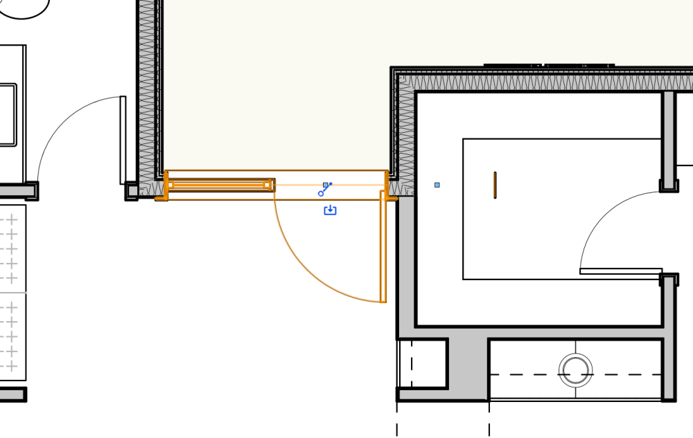
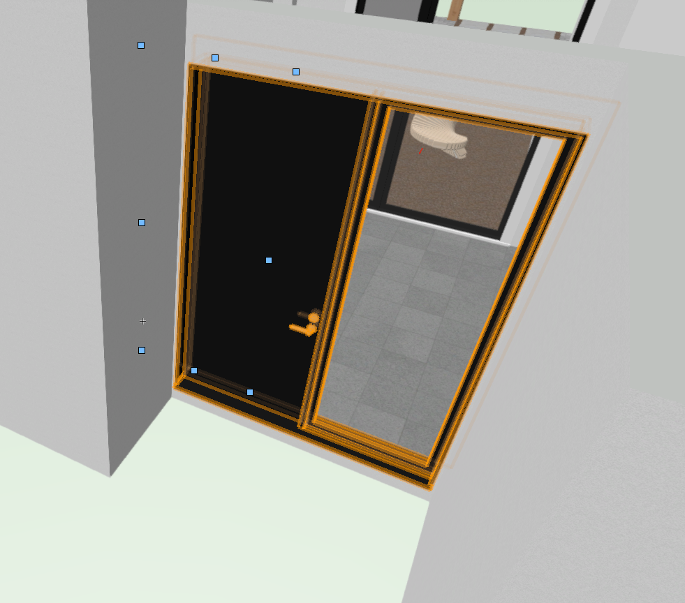
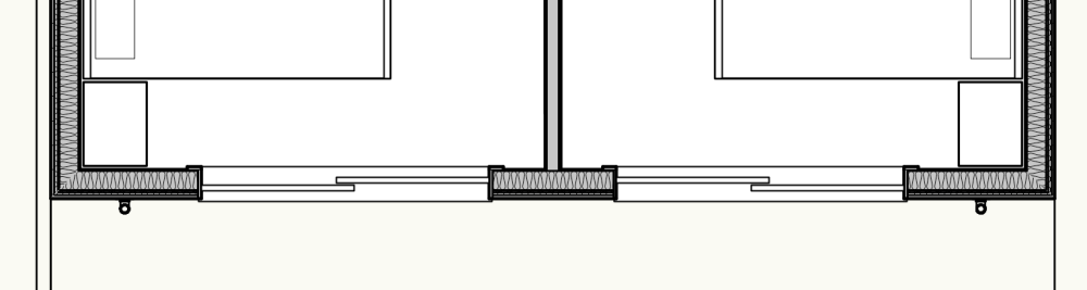
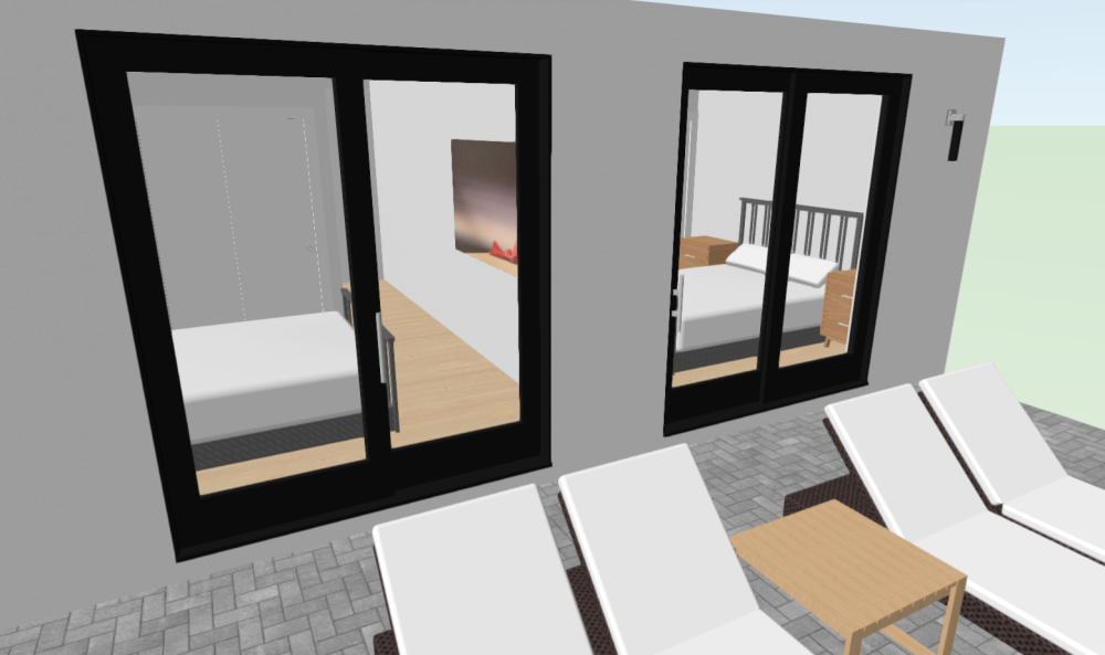
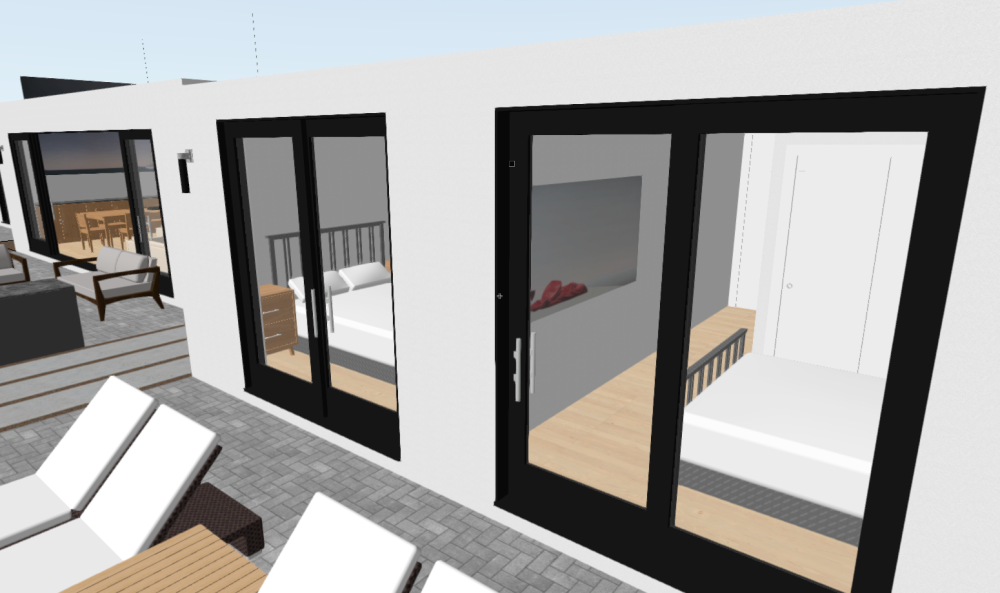
I'm having a similar problem with door hardware on sliding doors. In some instances, the hardware is correctly shown on the jamb side at the interior of the operating panel. But, in some cases it is shown on the operating panel where it overlaps the exterior fixed panel. Which is, of course, impossible. Here is a screen shot of two mirror image sliding doors in plan. The door on the left has the operating panel on the right, so the hardware should be next to the right jamb. The door on the right has the operating panel on the left, so the hardware should be next to the left jamb. Here is a shot of the exterior in 3D from one side. And then from the other. The sliding door on the left is clearly wrong. No amount of flipping the door or modifying the settings will get that door handle in the right spot. I'm using Vectorworks 2024 on Sonoma. I've just checked and I'm using the most up to date version.
-
Linking Record formats to referenced Excel worksheets
Jesse Cogswell replied to Tim Harland's topic in General Discussion
Good morning, friends. I made a quick revision to the Link Worksheet to Record command linked above. I added a checkbox to Show Hidden Records. This lets you link a worksheet to the parametric records of Plug-in Objects, which should allow for you to more easily control parametric objects using worksheets. Download instructions are the same as listed above. Link Worksheet to Record.zip
-
@Andrew Lees there are a lot of things that can affect the quality of a scan and your software’s interpretation of the data collected. 62mm is pretty accurate for the technology currently. Moving smoothly and without rapid changes in direction/twisting seems to produce the best results. Incidentally, I have the best results outdoors by moving up and down slopes rather than along them. Indoors I pretend I’m spray texture with the iPad and have good results.
-
Bug with inserting code into forum posts
Pat Stanford replied to Jesse Cogswell's question in Forum Feedback
@JuanP Any leads on why CH_R( without the underscore causes a 404 error on the Forum when trying to post? -
Bug with inserting code into forum posts
Jesse Cogswell replied to Jesse Cogswell's question in Forum Feedback
Any movement on this? This has been a huge bummer for sharing scripts for users. I have to either post the code directly with extra spaces inserted and instructions to remove them, or I have to encrypt the plug-in so that the combination of letters doesn't directly appear, which is less than helpful if someone wants to see the code behind the plug-in for modification / learning purposes. -
CONVERTING SINGLE LINE TEXT TO MULTILINE TEXT BOX
Jesse Cogswell replied to ASydDesigns's topic in General Discussion
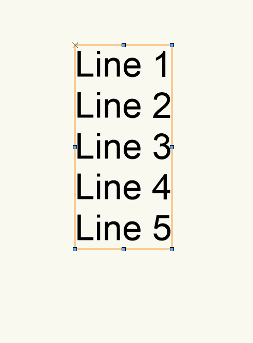
I wrote up a quick little script that will do this for you. It requires that you have more than one Text object to be selected. When the script is run, it will create a database of all currently selected Text boxes within the current parent container (Group, Symbol, Viewport Annotation, or Layer), sort them by Y dimension, and then add the contents of the Text boxes to the top-most Text box and delete the originals. Test Objects: Resulting Text Box: Keep in mind that the resulting multi-line Text object will have the same formatting as the original top-most Text object, the other Text objects' formatting will be forgotten. This includes things like Wrap Text and Width. Normally I would just post the code itself since it's so simple, but because it uses the dreaded combination of characters to add the carriage return, I've instead just attached the menu command .vsm itself. Installation instructions are as follows: Download the attached Combine Text Boxes.vsm file Place file within your User Folder in the Plug-ins folder To easily get to this, open up your Vectorworks Preferences Go to the User Folder tab Click on the Explore button (Windows), or Open in Finder button (Mac) Restart Vectorworks Once restarted, you will need to add the script to your workspace. Go to Tools - Workspaces - Edit Current Workspace Select the Menus tab In the box on the left, navigate to and expand the JNC category In the box on the right, find a menu you'd like the command to be placed in, such as Modify or Tools or Text Click and drag the Combine Text Boxes command from the box on the left to the desired menu in the box on the right. Click OK to accept the changes and close the Workspace Editor. Let me know if you have any trouble getting this to work or if is produces unexpected results. Combine Text Boxes.vsm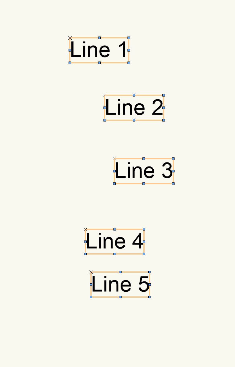
-
I don't believe that there is a scriptable way to change workspaces. If Stream deck offers a way to click as a specific location you might be able to get it to select the workspace you want.
-
 1) The selection tool is once again reverting to Lasso Marquee Mode on reboot. I quit with it on Rectangular Marquee Mode, and that's what I want when I boot Vectorworks. This was broken in the past, fixed, and now it's broken again. 2) Retain the sort order of layers. 3) Retain the sort order of sheet layers.
 -
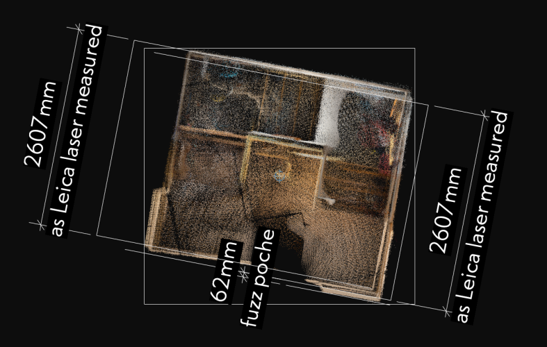
Okay, I've run my little experiment on a simple space. The attached is a small stairwell in which I also took a key dimension using a Leica Disto. Confirms it is the inner face of wall points that denote the surface, with - in this case - 62mm of poche wall thickness (compared to the 200mm in my earlier marked up screenshot). What is also interesting is the amount of drift even in this small space - I have two alignments of the walls. It would be interesting to see if this could be improved by using a tripod and making sweeps from a fixed point.
-
Is there a script to switch between workspaces? I work equally in Spotlight and ConnectCad with 2 different workspaces. The goal would be for a hotkey or a streamdeck button to switch workspaces quickly. Thanks
-
 BenS joined the community
 -
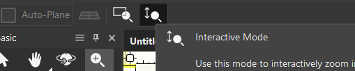
Have you tried changing the zoom tool's mode to interactive? What happens? I haven't tried it with a stylus.
-
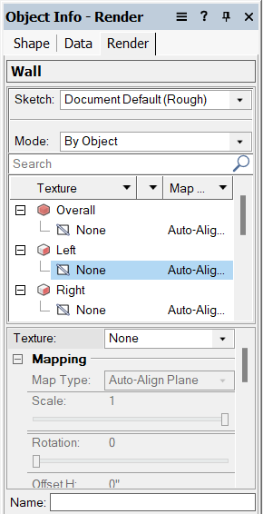
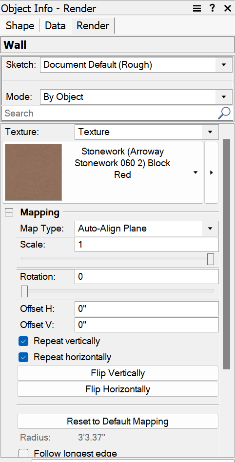
Hi there, I have created some walls using the Wall Tool and am trying to apply a renderworks texture to it. However, only the perimeter faces have the texture applied. In the Object Info - Render palette, a lot of settings that I'm used to seeing are now missing: The first image on the left is what my coworker sees, and what I'm used to seeing; a dropdown of applying textures to the overall or to specific faces. I, on the other hand, am experiencing the second image on the right, which is missing this whole dropdown entirely. I'm unsure if there was a setting that got changed or something, but we just recently upgraded our hardware at our office and have a fresh install of Vectorworks, and this has only started to become an issue with the new computer I'm operating on. Thank you!
-

when I open the AI visualizer, the dialog box is blank?
JuanP replied to grant_PD's topic in AI Visualizer
@MHBrown Based on your post, it appears that everything is set up for you to begin using this new feature. Please ensure that you are logged into Vectorworks with the license that has Service Select permissions, restart Vectorworks, and give it another try. If you encounter any further issues, let me know jalmansa@vectorworks.net, and I'll gladly connect you with one of our Tech Support Specialists for additional troubleshooting. Thanks -
Plant tick marks and .dwg exports shifting if not at 0 degrees view rotation
JuanP replied to DSmith2300's question in Troubleshooting
Hi everyone, I've just received an update from our R+D team regarding this issue. It's scheduled to be resolved in Update 6, expected in July 2024. -
 ü0ei3jow joined the community
 -
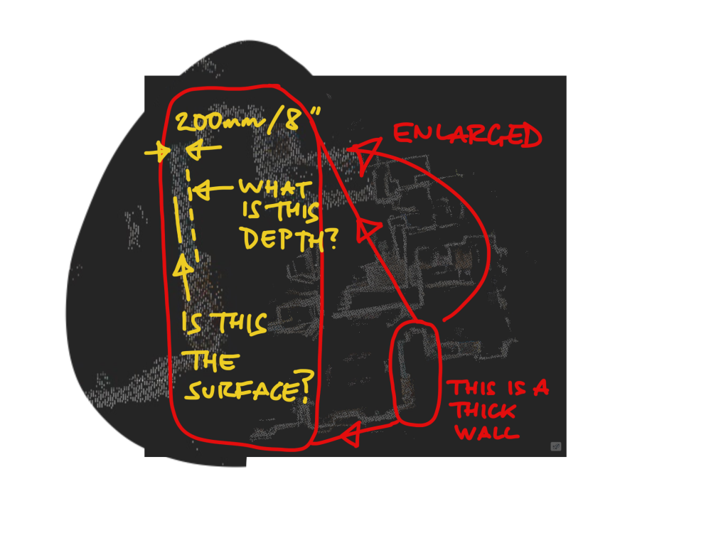
Picked up messing around with this Lidar scan again and I wonder if anyone can enlighten me about this 200mm / 8" thick "fuzz" that makes up the scanned walls? What is this? Is it generated to create a gestural wall thickness to make the scan more legible? Am I right to assume that the outermost (if considered from the wall) or innermost (if considered from the room space) surface of dots is the actual scanned surface? Hopefully my little annotated screenshot clarifies what I am talking about - the dashed line being the fuzz depth (as I have called it). The issue is particularly clear I think in this scan as it is a massive masonry wall in an old building which scales at over 1200mm thick outer dots to outer dots. I think I will experiment with a new scan in my immediate environment to see if I can figure this out. But any suggestions welcomed.