
All Activity
- Past hour
-
 Two points: Make a template file set up with everything you could need. Our standard template has probably 20 layers in for 10ish trusses, cable bridges, several LED video layers, lighting floor package, PA etc, plus utility layers to contain venue overlays, datums and other boring stuff. All of our standard viewports have the right visibilities turned on ready - so our rigging plot sheet layer has venue, truss and hoists visible and fixtures hidden. Get in to the auto-classing options in Spotlight Preferences. We have it auto-class truss, fixtures and rigging loads automatically, so we generally don't need to create classes much unless something weird comes up. If you're wanting to get more in to efficiency and automation, have a look at scripting with Python. (I say Python rather than Vectorscript as there is so much more learning resource for it on the internet, and it's great). It seems complicated to people that haven't coded before (it did to me last year when I started) but now I've written a ton of business-specific plugins that do exactly what I want. I have ones that can automatically change class and layer visibility for a new viewport in a few clicks, based on our specific content and classing structure. You need to have a really solid standard class and layer structure first for it to be worth it though. Some people say that it shouldn't get to needing scripting, but our industry has as many opinions as there are people that work in it, and rather than the software having 'one' way of working, it's nice that if you really want to make it work your way, you can.
 -

plan shows up in viewport but not in design layers
Landartma replied to Landartma's question in Troubleshooting
And there it is. Thanks I knew I was missing something simple. - Today
-
I suspect you're trying to pull data from both schematic devices and panel connector objects, which won't work. Database rows work on the basis of reporting a given item, and data about that item. You can't pull data about two items in to a single row. Can you post a screenshot of the database builder dialog? i.e. right click the '2' on the left hand side and edit it. I think there might be a way to do what you're trying to do by reporting on the Panel Connector rather than Device, because I think there are some eval functions for Panel Connectors to lookup associated device information. If you can upload the screenshot I'll take a look.
-

Wood Truss Tool
The Hamma replied to Sam Combs, AIA, NCARB's question in Wishlist - Feature and Content Requests
@Sam Combs, AIA, NCARB I made a tool to make a schematic truss. It’s definitely not structural by any means but it’ll make a 2D and a 3D Truss Schematic Wood Truss.vso- 1 reply
-
- 1
-

-
 Showuav joined the community
 -
I have written this script and it creates a new viewport. But it stops looping after the first object. It is supposed to move all the annotation objects from the selected Section VP to the new viewport PROCEDURE ConvertSectionVP; {$debug} VAR H1,H2,H3,HVP,HVP1:HANDLE; Result:BOOLEAN; PROCEDURE CopytoNewVP(h :HANDLE); BEGIN H1:= GetVPGroup(H,2); H2:=FInGroup(H1); WHILE H2 <> NIL DO BEGIN Result:=AddVPAnnotationObject(HVP,H2); H2:=NextObj(H2); END; END; BEGIN HVP:=CreateVP(ActLayer); HVP1:= GetVPGroup(HVP,2); ForEachObject(CopytoNewVP,((((ST=SECTVIEWPORT) & (VSEL=TRUE))))); END; RUN(ConvertSectionVP); PROCEDURE ConvertSectionVP; {$debug} VAR H1,H2,H3,HVP,HVP1:HANDLE; Result:BOOLEAN; PROCEDURE CopytoNewVP(h :HANDLE); BEGIN H1:= GetVPGroup(H,2); H2:=FInGroup(H1); WHILE H2 <> NIL DO BEGIN Result:=AddVPAnnotationObject(HVP,H2); H2:=NextObj(H2); END; END; BEGIN HVP:=CreateVP(ActLayer); HVP1:= GetVPGroup(HVP,2); ForEachObject(CopytoNewVP,((((ST=SECTVIEWPORT) & (VSEL=TRUE))))); END; RUN(ConvertSectionVP); Cat Office Millwork Test.vwx
-
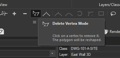
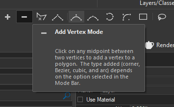
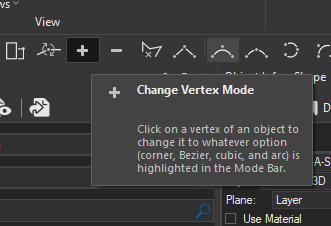
The tool mode icons in the polyline reshape mode are wrong.
-
Is it possible to have a plug in object get the rotation of another object already in the drawing and use that as it's own rotation? Plug in object A is at ptX,ptY with Roation R for plug in object B I'm able to read ptX, ptY, and Roation R of object A. But I can't figure out how to set the rotation of plug in object B to something relative to plug in object A. Any ideas
-
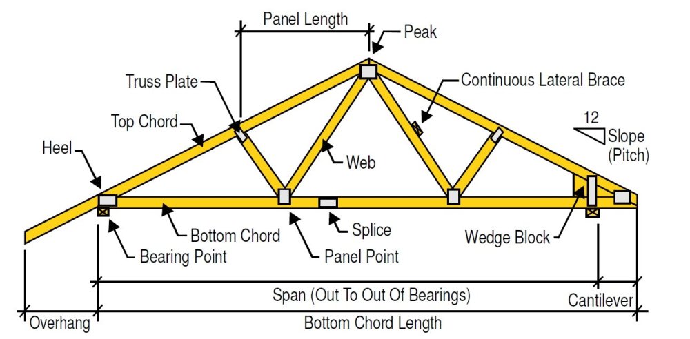
I've been using MiniCAD/Vectorworks now for over a quarter century and I've always wanted a 3D wood truss tool. That is, one that is modifiable for a pitched roof, one that shows the different diagonal/vertical web pieces, one that can be a half truss, etc. It is about time that this feature be added to Vectorworks and is hereby requested for an update or for Vectorworks 2025. See below.
-
Don't use contours when you have points, points are truth... contours are interpretations of truth. You should be able to clean up and decimate your point file in Metashape. Then export it to a .las file which can be imported into Vectorworks. Once you have it in VWX, you convert the .las point cloud into 3D loci. Those can be used to make your site mode. I placed point on top of your site model. That's not going to be as accurate as you doing all of this in Metashape.
-
Yeah you're right, that was the wrong example, it's my *objects classes that would be gaining the extra appendage. But some of them are similarly complex and are already hyphenated several times.
-
But you wouldn't be assigning Components to construction status classes would you...? Wouldn't the classes be *objects-walls-internal-existing, *objects-walls-internal-demolished + *objects-walls-internal-proposed? If you didn't find it necessary to differentiate between internal + external walls (I don't) it could just be *objects-walls-existing, *objects-walls-demolished + *objects-walls-proposed.
-
I have prefixes for classes like *objects- and *materials-. Typically a wall will be in something like *objects-walls-internal And its components in eg. *materials-masonry-brick-yellow_stock One of the reasons I'm reluctant to use classes to designate existing/demolished/new is that I would then end up with classes like *materials-masonry-brick-yellow_stock-new - but VW only recognises the first 3 hyphens (I think) and any more you use after that don't get collapsed in the class organisation dialogue so it becomes rather unwieldy. I can see that using brackets could be a clever way of giving oneself another level of hierarchy though...for objects [walls] [doors] but for materials {masonry-brick} {timber-rough-softwood} or something like that. But...then I wouldn't be able to collapse away all material or all object classes as I can now.
-
 That would work. I already have quite a few 'mostly off' classes for data. Might be a wish list... It would certainly be cleaner to be able to store images as data directly in a symbol or a record format.
 -
Jeff, A much needed Master Class, sincere thanks for your time and patience. Believe it or not, I have researched this whole issue of importing topo data, creating VW topo, creating site models, etc., but nowhere did I find the mention or coherent explanation that you gave. Being pretty new to me, all this is just trial by error... In order to create a better, more proper result (and learn by doing!-), I will create a new file, using points, as you suggest. You mention in your example "This model was made by placing points on your site model at a 5' interval." Again, being new territory for me, could you please expand on the best way to do this (or refer to good source)? (again, could not find relevant, understandable direction on YouTube or otherwise online. PS I flew the site with a drone (first time doing so) and I believe the optical resolution was some fraction of a centimeter. To prove how in the dark I am about all this, I then brought the aerial photos into Agisoft Metashape Pro where I created the topo. From there, I brought it into QGIS (couldn't get Metashape to export and VW to import successfully) from which I exported to VW as a shape file, if I recall correctly. In other words, knowing how to do points directly will be much quicker, with, as you say, much better results. Thanks!
-
There are lots of ways to get shapes like that. If you look at most flowers, their shapes have some kind of symmetry at a basic level. Once you figure out that symmetry, break it down into curves to use as Lofts or Revolve with Rail. Once a basic petal is developed, you can use the deformation tools to bend and twist to make unique iterations. Here's a video of both a tubular and a composite flower. flowers.mov
-

Is there a way to add an image to a record format?
Tom W. replied to hollister design Studio's topic in General Discussion
You could include a product image in the Top Component of a hybrid symbol + put this in its own class then choose to display this in a Graphic Legend by using Hybrid Object Display + making that class visible... So this particular 2D Component would not be displayed anywhere else (the class would be permanently off), its only purpose would be for display in Graphic Legends. -
I was wondering if there was a work around to attach a product image to a symbol or to a record format. Would be nice if one could grab an image from data to display in a graphic legend listing hardware etc. - similar to how plant objects can contain images.
-
basic shape!! how did you get the nice curves on the edges? thanks a bunch!
-
 kshih joined the community
 -
DBrown, I suppose the developers are too busy working on clickbait AI advances rather than actually working on and improving the core requirements of a BIM program...
-
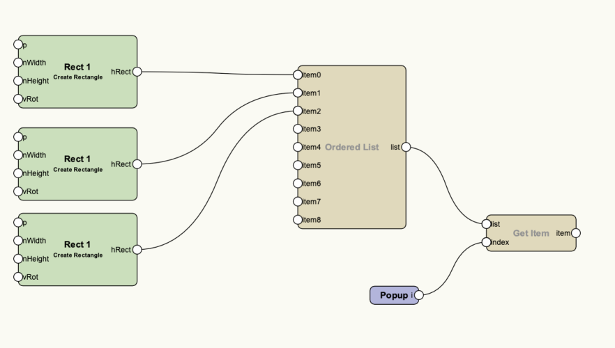
Hi, I'm trying to create a marionette script that will allow me to select a choice from a list and only produce the item selected via the list. The example I'm showing would be 3 different rectangles. I've put them into an ordered list. I've created a popup and used it as an index. when i run the script it proceeds to create all 3 objects rather than just the indexed item. Is there something else that I'm missing? Thank you Derek
-
I am trying to get a report to output the Plate/Panel Device name, Device Type and the ports that are on that panel with their display tag and I am able to get the Panel info, but for some reason the reports are not giving me a single report with all the information in a single place.

-
I ended up getting a MSI Stealth 16 AI Studio, 96GB RAM, I9 Ultra 185H, RTX 4070. I did not make the jump all the way to ARC, but I can turn off the 4070 for reduced power consumption. I am actually drawing on it for the first time right now, so i have not really gotten to put it through its paces. I draw for the entertainment industry, mostly cruiseline and amusement park shows. I do some rendering, but it is not the main focus of my work. I bridge the gap between design and technical. Depending on the day and who is paying for my work, I range from designing the pretty pictures, to doing construction drawings for the shop floor, to doing storage layouts of the finished product when there is more than one show using the theatre. So far the machine is a bit warm, but not hot. It is quiet as well, which runs counter to a complaint I have often heard of on MSI machines. My screen is a bit smaller, and the keyboard layout is a bit different form what I am used to but I should adapt to that fairly quickly. Now I have room in my bag to bring a second screen so ultimately i will probably have 75% more screen real estate than i used to have. i still need to figure out how to change the twinkling backlight of the keyboard. All told, though, it weights enough less than my old laptop that i can pack a second screen and my Streamdeck XL and still be lighter than what my old rig weighs. This machine is mainly for when I travel to installations or do site surveys. My desktop is where most of my work happens, but travel has become such a regular part of my work that this has become necessary. It is not uncommon for me to be away from home for a month at a time.
-
One more simple request, if you are willing to add the “security” category, perhaps you can instead add “access control”, “CCTV” or “surveillance”, and “security/fire alarm”? It would be useful to have the categories more granular, since “security” is an umbrella for all these subsystems. Thanks again.
-
Thanks, @Conrad Preen!
-
Hi, I'm afraid you will have to jump through several hoops to achieve this, the Wall tool in Vectorworks is too simplistic and dumb to accomplish this directly, you can't have even stacked components, slanted walls or different shaped walls . For the walls with odd shapes I recommend to use the Pilar tool combined with walls of different thickness connected together


