
Jeff Prince
-
Posts
3,151 -
Joined


.thumb.jpeg.48a6fdc44e48c98b8e1b507e86e57e95.jpeg)


Recent Profile Visitors
22,364 profile views


-
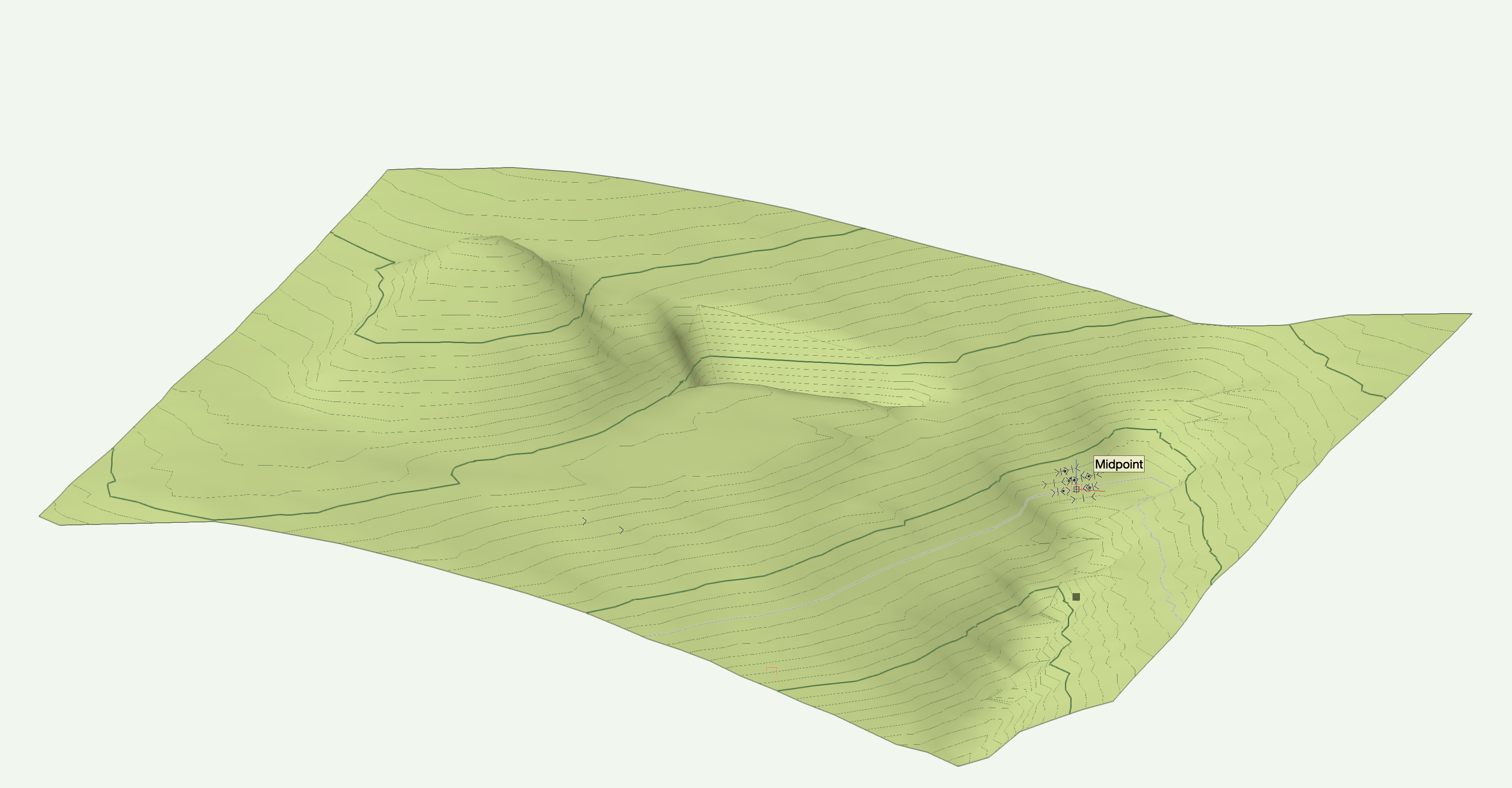
Don't use contours when you have points, points are truth... contours are interpretations of truth. You should be able to clean up and decimate your point file in Metashape. Then export it to a .las file which can be imported into Vectorworks. Once you have it in VWX, you convert the .las point cloud into 3D loci. Those can be used to make your site mode. I placed point on top of your site model. That's not going to be as accurate as you doing all of this in Metashape.
-
There are lots of ways to get shapes like that. If you look at most flowers, their shapes have some kind of symmetry at a basic level. Once you figure out that symmetry, break it down into curves to use as Lofts or Revolve with Rail. Once a basic petal is developed, you can use the deformation tools to bend and twist to make unique iterations. Here's a video of both a tubular and a composite flower. flowers.mov
-
Post your file and explain how you want things reported. In all likelihood it is a simple error in the criteria for the worksheet that is causing you grief.
-
That would be a very valuable tool. @Tom W. has done several old buildings with irregular forms, his advice would be helpful to you I'm sure.
-
How you solve this will depend on your desired outputs. If you want a functional BIM model with the ability to quantify walls, add doors and windows, and develop interior elevations... you'll have the best results with the Wall tool and will have to learn the different modes and closures to get the best shape and appearance. It will take some effort (issue 1), but it's possible once you have the experience. If you can get by with modeled walls, you can still place doors and windows in such a model, you just have to subtract holes from those walls to fit the desired elements (solves issue 4). For the modeled wall to read in plan, you turn it into an AutoHybrid, which allows you to give 2D graphic qualities to 3D objects (solves issue 3). If you model your walls, best to do them all the same way, then you can "join" them using Solid Addition (solves issue 2). You can't join a Wall with a Solid object.
-
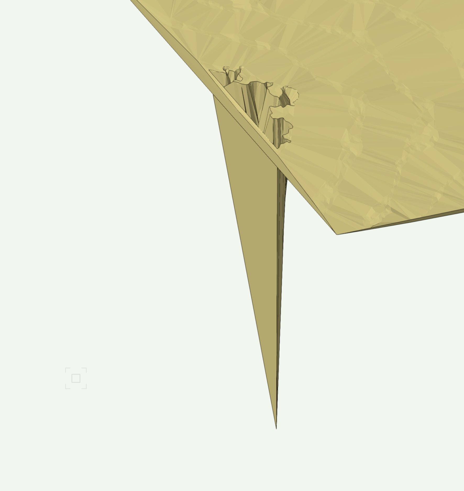
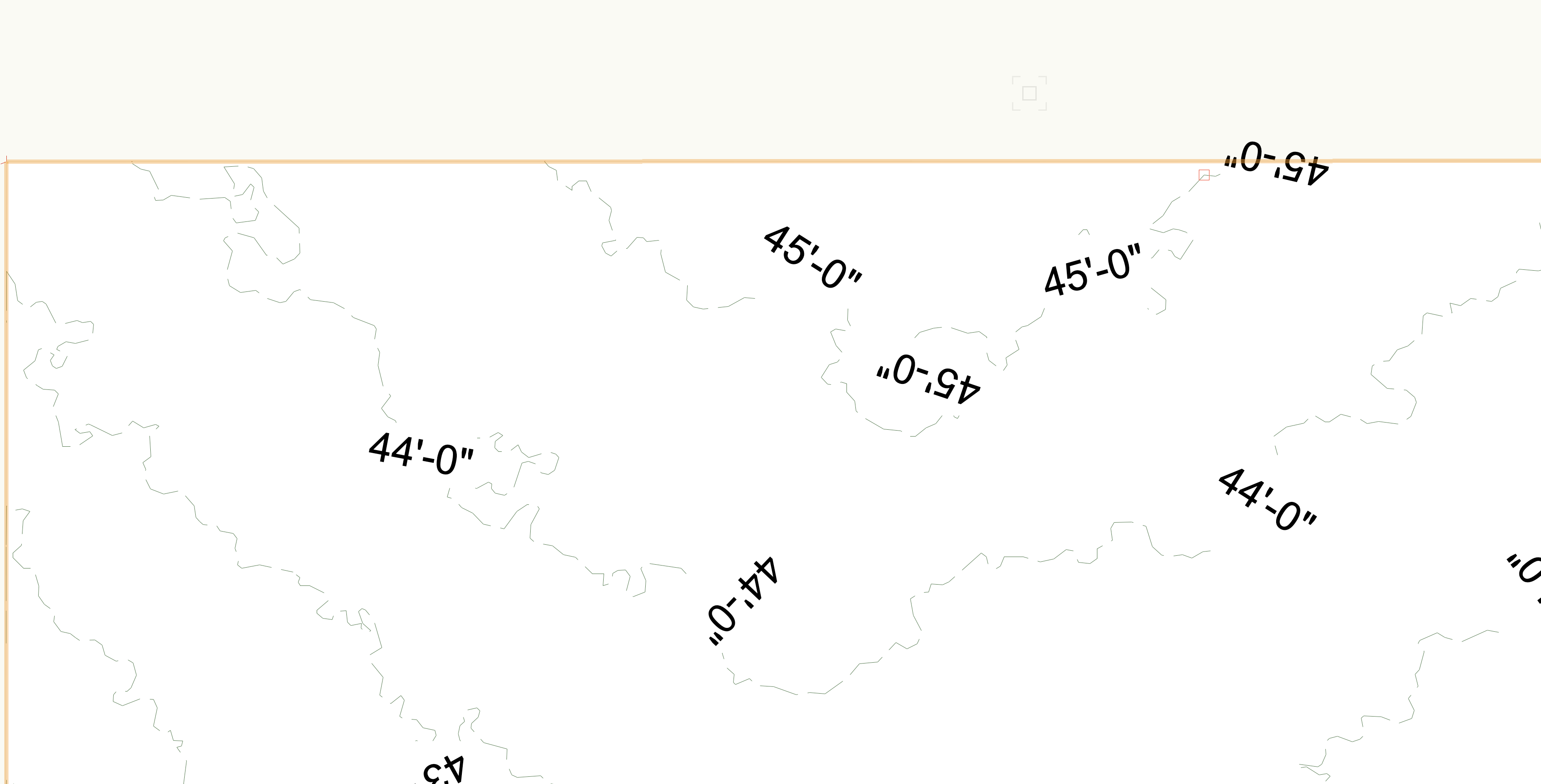
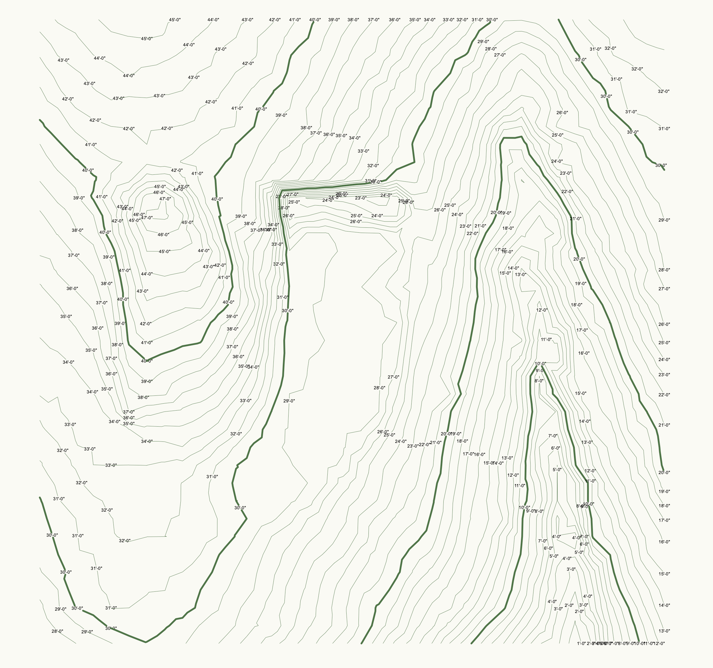
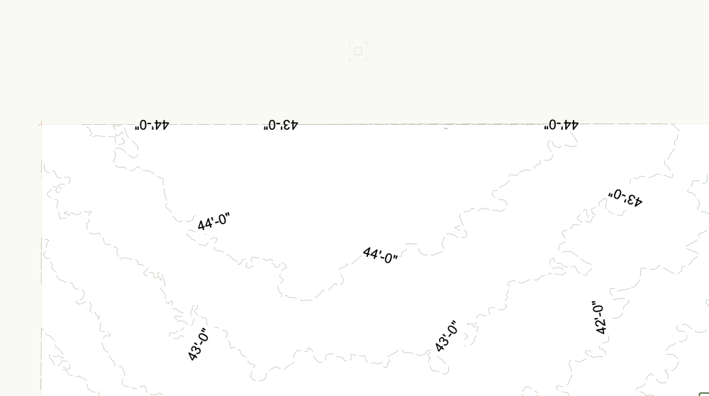
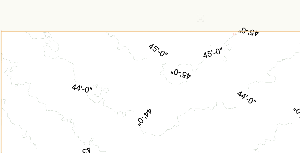
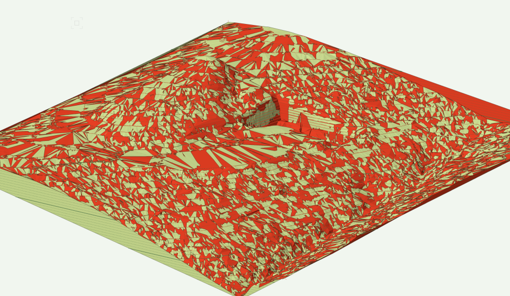
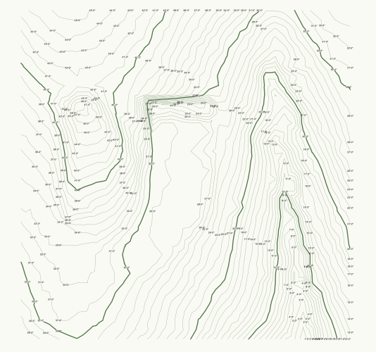
You have two tiny polygons sitting at z=0 at the tip of the anomaly. Your previous posted file does not contain that extraneous geometry. Delete those and the problem goes away. In the future, you should post both the file with the issue AND images depicting what you are experiencing because it helps folks like me understand your problem better. Otherwise, you might not get good advice, like that bug report being filed. Before adding points After adding a couple of points... In terms of getting the 45' contour to show up, you could add a couple of 3d loci at the edge of the model at 45.5' and this will correct the VWX calculation. Your contours are just so overly complicated, it's probably tripping up the DTM modeler as it tries to connect the zillions of points you have provided with tons of near intersecting triangles being created. It looks like your contours were developed from a drone based photogrammetry project and not a LiDAR scan. Where did you get the survey data and why didn't you use points instead? It's hard to believe the contours represent the actual site conditions with so many little and insignificant wiggles in the lines that are not from drainage. I would run the simplification routine on those and reduce the number of points and try to straighten them up. I did a simplification using 6" and it dropped your site model from 26MB to 5MB with little graphic difference between the models. Green is your data, Red is the refined. This graphic shows they are essentially coplanar. And then there is the proper way to do these things... With points instead of contours. This model was made by placing points on your site model at a 5' interval (something a surveyor will typically provide). The resulting model is 1.7 MB and easily takes site modifiers without problem like your models will have when you add a site modifier, texture overlay, etc. Plus, a points based model makes much nicer contours. Here's my nimble points based model. It will outperform your unnecessarily detailed model and produce more accurate results all day long. Legible and correct contours when you don't overload Vectorworks with unnecessary contours or high levels of detail.


-
Sometimes it’s faster and more fun to make things in real life and then scan them when you need something like the images you shared.
-
Your file does not include a site model. You are using high resolution contours with creates no advantage for your work.
-
use the deformation tool Bend
-
Use a different mesh editing program that can preserve the texture, VWX can't do it. Blender, Rhino, Meshlab, etc...
-
When that time comes, get something top tier. You won’t regret it. I bought a near maxed out MacBook Pro in 2015 and just retired it simply because I didn’t need a laptop and thought someone else could get good use out of it for a few more years. It still did everything fine, including twin motion animations. in terms of operating cost, it was only $350 a year for its service life! As a landscape architect, I appreciate having a fast computer to deal with the complicated 2d graphic of plants and hatches along with the highly complex 3rd party plant models I like to use in my renderings. Nothing worse than working on a slow computer. Oddly, I have not seen large improvements in VWX graphic speed since they overhauled the VGM back in 2019? The latest hardware is good, but not earth shattering good as we were led to believe by some software vendors.
-
There are many ways to do this and the best way probably depends on what your end goals are. There is a pretty good class on VWX uni that addresses this topic and using data visualizations to display the status in different plans.
-
you make them parallel to each other and use the same cross section, not leaving it to chance 🙂
-
That example I posted earlier solves these seam issues. You can convert the pieces to solids if needed.
-
I'm a long time former AutoCAD user. You'll really prefer Vectorwork's method of hatching once you figure it out. 1. draw your polyline as a continuous boundary. 2. assign a fill to it. The resulting object is singular, gone are the days of having a separate boundary object and hatch object. Your boundary is not continuous or closed, so it tries to close itself with the fill you are seeing. Attached is a file with some 2D hatch examples and 3D hardscapes for you to check out. hatch and hardscape examples.vwx