


TeeMuki
-
Posts
29 -
Joined
-
Last visited
-
DWG export creates blocks out of Hardscape and Landscape areas
TeeMuki posted a topic in Site Design
Hi, Our office mainly provide our files to other designers etc. as dwg files. The dream file for sharing would have symbols as blocks, then surface borders as polylines and surface areas as hatches. When we export Hardscape- and Landscape-objects into dwg-files, they convert into blocks. We would definitely prefer that they would convert to polylines and hatches. Because the file includes a lot of different blocks, the process of exploding all the hard- and landscape-areas takes time. Which settings should we use that they don't convert into Blocks? It is a huge problem when the objects are not converted in the right way into dwg and consumes our time when we clean the files in autocad before sending! -
It’s the same with both 😞
-
The data should be completely open to use. With QGIS atleast the same service portal url works completely fine. To your first question i don't have the answer 😞 Maybe @Esa K has?
-
Thank you for your quick answer @Tamsin Slatter ❤️ I did try it, but couldn't get it work that way neither. What am i missing now, i guess there is some way to do this easily with a symbol and with a stake object, i just don't find the solution. I found some old files from this forum with some scripted databases and tags, those did not work the way i was hoping for. They did show the symbols basepoint coordinates, and i need to show 2 different points of the symbol. Honestly i'm trying to find some easier solution to this with the Stake Tool because the capability is there clearly!
-
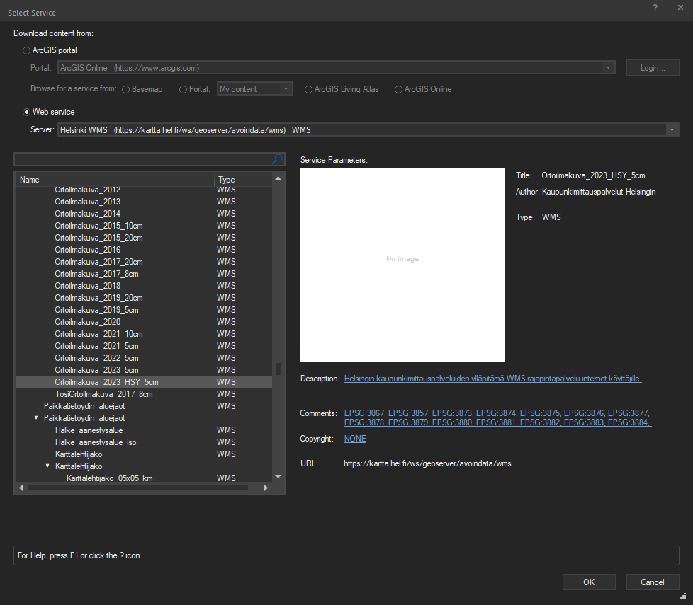
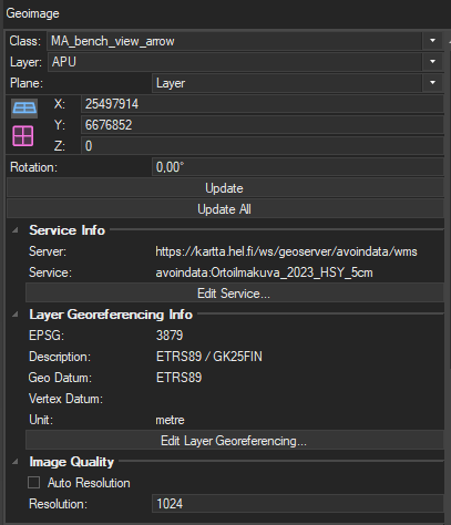
Hi! I will reply here, even i don't have the answer to you :(. I have tried to add Helsinki WMS and WFS servers to Vectorworks, but i can't get them work. It does find the data from the servers as in the picture below is visible, but when i try to download them it says "Unsupported service type. Select a different service." Below settings from the OIP: Would be really nice to get this tool to work properly!
-
I’ve tried to use open data provided by different cities in Finland trough WMS and WFS urls, but i can’t get them to work at all with Vectorworks. With my current project i have downloaded the material in shapefiles and imported them to Vectorworks then. That works well. I had no clue why the GIS data is not working, but i guess its the same as you said with the GML :(.
-
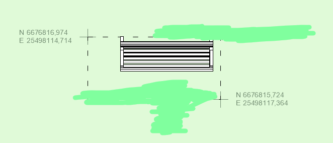
Hello, Is there some easy way to get the coordinates in to a symbol? So when you place a symbol it would show the true coordinates on top of the symbol? Stake object does it, but when i put them inside the symbol they don't update the coordinates anymore. If i group the symbol and the stake then it works but for the workflow it would be better inside the object... The picture below shows the desired outcome made by grouping the symbol and the stakes. I'm new to linking text with records, but i haven't found a way to do this. Stake Tool is great, but it feels weird that i can't take the use of it fully... I appreciate if someone has time to help me!
-
To particularise this better... I'm trying to achieve the most fluent workflow in BIM with relative big design areas. To give some insight of the scale, i have currently in my project: 60 000 m2 Landscape areas 60 000 m2 Hardscape areas 1100 Trees 250 000 m2 Site Model area I'm running a quite high-end Laptop, but the scale of this project and BIM is taking the best of it 😄 Somehow i feel like Vwx is not utilising my computer as it should. Often the cpu and gpu are running with low usage... I'm running Vwx 2024 3.1 now, but i think the performance has been worse since a few updates. The project was running better in my opinion with the first 2024 patch. But this is hard to compare, just a feeling... My computer specs: Intel i7-13800H (14 cores (6P + 8E), 20 threads, max frequency 5.20 GHz) 32 GB ram 5600 MHz NVIDIA RTX 3500 12 GB VRAM I'm trying to find solutions to make this project run as smoothly as possible. I appreciate all the help i can get! ❤️ Does @Katarina Ollikainen maybe have some input to this Landscape area setting? 😇
-
This is somehow related to the topic, so i'll ask here... I'm currently trying to make one large design area to work as fluently as possible. I have noticed that the large amount of Hardscapes are the most demanding ones to run smoothly, but now im also encountering some issues with the different Landscape areas. I have some memory trace that the Landscape areas setting 3D Display - 3D Polygon would be the "lightest" way to go, but have some one done some research on that? So which of these is the better (lighter) way to use: - 3D Display - 3D Polygon - 3D Display - Texture Bed Thank you!
-
Yes i am 🙂 Send me a message, if you still need some help!
-
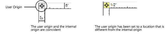
Hi, i'm not sure how you did set up your file Georeferencing. But here are few tips. If you get the project coordinate point from the architects, you set them in the Georeferencing tab in the Northing / Easting points. You have to also set up the EPSG correctly, in Finland i'm mostly using GK25FIN (EPSG 3879) or GK24FIN (EPSG 3878), but that is what you have to ask from the architects. Then you add the possible rotation there also, but that you will also get from the architects if they have used some rotation. After this your Georeferencing is set to the same point as Architects. If you double click the left upper corner from the rulers (picture below), you get the origin preferences. If you add some references from the city, you use the "Georeferenced option" and the rulers will show your coordinates in "world". If you add some references from the architects, you use the "Set user origin to internal origin" then your rulers show your coordinates located in 0,0 -point the same way as the architects project coordinate. Hopefully this helps!
-
Workaround for exporting site model to landxml.
TeeMuki replied to Knut Andreas's topic in Site Design
Just a thought… Have you tried site model to ifc? I assume you can import the ifc to Civil? 🙂 -
Thank you for your input! I have also done that in the past, but im trying to figure out now, how to work with the Path -modifier as efficiently as possible. Sometimes, or even sadly often, the Aligned is not aligning to the surrounding site modifiers. To get the work done i'm changing it to a 3D-poly and setting up the Vertexes correctly manually. What can cause this? Are the lines not on top of each other, or are they maybe going over each other boundaries? Im often using the bucket tool, so the edges of the modifiers should really go flawless together... Any ideas? Thank you!
-
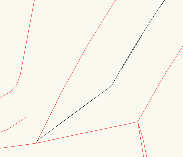
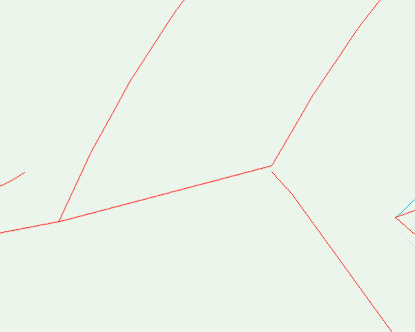
Hello, The Path Modifier is mostly working really well in Vectorworks 2024. But the modifier seems to do some weird slope at the end of the modifier, sometimes on one end sometimes on both ends. I took a screenshot of what i mean. On the first picture you can see that the middle line of the path modifier is going to the left corner, and that corner is on the set elevation. The right corner is because of that on a higher elevation (2nd picture of the 3D view), even i don't have set the Transverse elevation (sideslope) on the path. So why it does this and how can i fix this? And why is the another end of the Path Modifier on even elevations? Alot of questions, thank you for your help!
-
Thank you, Unified View setting was compelety new to me. Now im just wondering how this got selected in the first place, since i haven't ever been in this tab... Maybe there is some shortcut for this, that i did press. It was weird that the "Enable legacy 2D features" was unchecked, but the Turn off unified view was checked. But unchecking the "Turn off unified view" did the thing. Thank you so much! ❤️
