twk
-
Posts
877 -
Joined
-
Last visited
8 Followers


.thumb.jpeg.48a6fdc44e48c98b8e1b507e86e57e95.jpeg)


Recent Profile Visitors
5,805 profile views


-
this has worked for me in the past. The variable passed in must strings in a tuple, be a type <tuple>. testing for classes, but can pass any handle that can be tagged (layer, etc): def tagthis(handle, value): if type(value) is tuple: vs.SetObjectTags(handle, value) elif type(value) is list: vs.SetObjectTags(handle, tuple(value)) elif type(value) in [str, float, int]: vs.SetObjectTags(handle, (str(value),)) else: raise ValueError("Incorrect type for Tags : <{}>".format(type(value))) h = vs.GetObject('TestClass') tagthis(h, ('tag1', 'tag2')) Just tested in VW2023 and VW2024, all working on this end
- 9 replies
-
- 1
-

-
- python
- vectorscript
- (and 2 more)
-

AI command interface for Vectorworks
twk replied to Christiaan's question in Wishlist - Feature and Content Requests
couldn't have said it better.. -
1) For your first post: The second parameter for the ForEachObject must be a criteria string. so: vs.ForEachObject(sel, "T=RECT" & "T=NURBSCURVE") should actually be written as: vs.ForEachObject(sel, '"T=RECT" & "T=NURBSCURVE"') 2) For your most recent post: why are you using VSEL and SEL? shouldn't just SEL work? tips: You could place criteria strings in variables: crit_string_1 = '"T=RECT" & "T=NURBSCURVE"' so it would be: vs.ForEachObject(sel, crit_string_1) and also leveraging pythons f-string capabilities: type_1 = 'RECT' type_2 = 'NURBSCURVE' crit_string_1 = f'"T={type_1}" & "T={type_2}"'
-
@Poot, yes have saved views in file, still no luck. Have you got it to work?
-
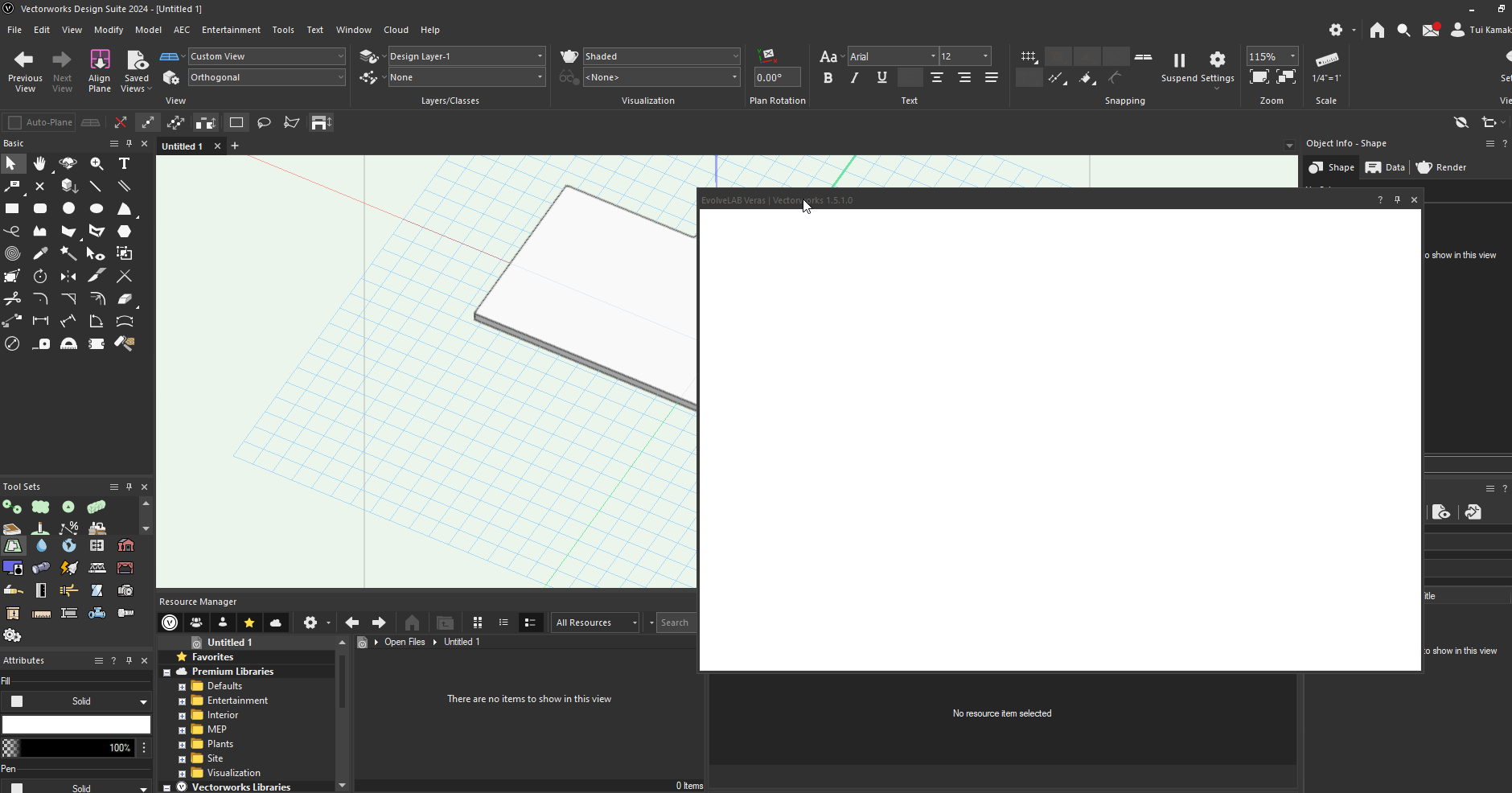
Great! @BenjaminGuler Have installed and tried running, but just have blank window when trying to run from the web palette (as per instructions)
-
Works now, cheers @LDraminski
-
@Gunther no place to enter promo code, and no email received either. Keen to see if anyone has actually got the promo to work.
-
Hmm, this was for 2023 before 2024 came out correct? Has anyone got the free promo to work? it isn't clear in the customer portal. It says click promo code, but that just takes you to a help file location on loggin in. No promo code provided. @Gunther any idea how to test this? Cheers and happy new years!

-
Ha!, Great minds think alike! Have implemented this as well. However the data manager settings are sporadic with project shared files. Sometimes saving and sometimes not. Continuing to test this.
-
Yes this is the work around we use at the moment. Wondering if we could tag an object or data tag, restricting tags to a certain class
-
Too little time to troubleshoot/read help file, anyone knows if its possible to tag objects based on their class? I have a generic data tag style setup that reports the area of any tagged object, however I want to only tag my footpaths, (classed as SITE-Foot Paths). Is this possible?
-
Ahh looks like Archicad beat VW to the punch..
-
the path has to be absolute when executing inside vectorworks. Not: filename = "output.csv" leaving it as "output.csv" is telling Vectorworks' python interpreter to save it the installation directory of vectorworks. Try specifying a full path to another location eg. filename = "C:\Temp\output.csv" Also look at DataFrames for python using the pandas module. It has better functionalites for Data Wrangling. You'll need to write your own module for converting a worksheet table to a pandas dataframe, then once its in dataframe format, you can do many things with that dataframe. Export to csv, xls, json, etc
-
Interesting... Confirming on Windows PC that am having the same behaviour as @WhoCanDo. VW2024 18.10.2023_12.29.12_REC.mp4 VW2023 18.10.2023_12.30.10_REC.mp4
-
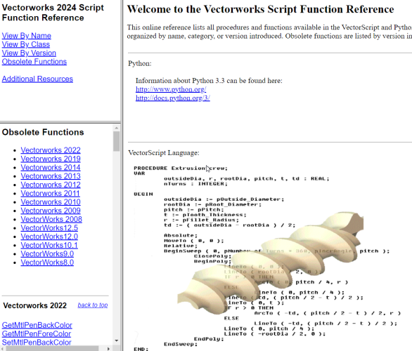
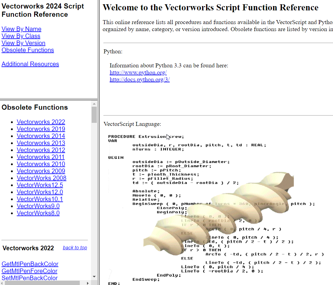
All versioned scripting functions are listed here (for python/vectorscript): https://developer.vectorworks.net/index.php/Vectorworks_Scripting#Version_Information Also the local file shipped with Vectorworks has the ability to see the obsolete functions and functions by Version: <Your Installation Location>\VWHelp\Script Reference\ScriptFunctionReference.html