


markdd
-
Posts
3,470 -
Joined
-
Last visited

.thumb.jpeg.48a6fdc44e48c98b8e1b507e86e57e95.jpeg)


Recent Profile Visitors
13,492 profile views


-
Others will no doubt chime in, but this is how I would approach creating the object in the image above. Interestingly, this throws up a bug with the Extrude Along Path Command. The Profile should twist around the Curve, and indeed, it does when the Helix Spiral is set to a radius setting of 20 and above. In the setting I eventually settled for (12), the Extrude along Path profile takes the shortest route, which is why the profile doesn't seem to twist as intended. Bug report on its way.....
-
No, I don't think so. However, you can make multiple selections using not just a rectangle but also the Lasso and polygon selection modes. These have got me out of most tight corners when it comes to selecting multiple vertices. There is a little-known shortcut when you activate the Reshape tool. If you then press option/alt key, the rectangular selector changes to the lasso, and you can be very specific about which vertices you want to select.
-
Right about Italics, Red and Blue text. A green object is a page-based object. If an object is a Plug-in and a Page-based object (Data Tag), then the Green colour wins!
-
Cutting round shapes out of objects - edges are rough
markdd replied to Harpahei's topic in Architecture
You probably have your Shaded Options Quality set to Low. Change it to High and you should be fine. I would strongly suggest you keep the 3D conversion Setting to Medium or High. Very High will generate unnecessary detail that you mostly will not need.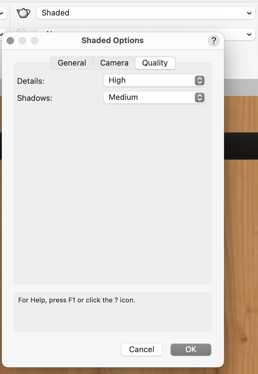
-
DataTag: function/formula to query another "Data Tag data field
markdd replied to Tobias Kern's topic in General Discussion
It's worth saying that the record is part of the Data Tag style. So when you add the Data Tag, the Record is automatically added as well—no extra work. Here is the file back that shows the field displaying 'Yes' if the Boolean result is True otherwise, it will show 'No" testfile yes:no.vwx -
DataTag: function/formula to query another "Data Tag data field
markdd replied to Tobias Kern's topic in General Discussion
There may be a cleverer way to do this, but to get the True/False value to the test field, I have added a Record to the Data Tag plug-in Style. Now, The Test Field will receive the True/False result, and you can hopefully run the IF formula using the result. Using Records as shuttles between one field and another via the Link to Calculated/User-entered field can be very useful. Here is the file back. testfile.vwx -
You don't need to draw a section line. The program will do it for you. The workflow is as follows: Select the Viewport on the Sheet Layer Menu > View > Create Section Viewport Define the cutting Line length and direction as normal A new section viewport will be created, and a Section Line will be added to the Annotations portion of the original Viewport.
-
Yes. Go to the Replace with Stock Symbols Command, and then when the appropriate Truss Symbols have been added, you need to run the Convert to Truss Command.
-
Making a smooth transition (in 3d) between two NURBS curves?
markdd replied to line-weight's topic in General Discussion
Here is a sample file showing a group of loci created by the Analysis tool using the same method I described above. Loci along a Curve.vwx -
Making a smooth transition (in 3d) between two NURBS curves?
markdd replied to line-weight's topic in General Discussion
If you are looking for control points at specific Z heights along NURBS Curve, then create a Nurbs Surface at each Z height and then make sure that the curve is covered by the Surfaces so that it intersects with them. Then, using the Add solids command, add all the surfaces together as one object, and run the Analysis tool on the Curve and then the Solid. You should get the locus points where you need them. -
How to Turn off an Accidental View Option or Tool
markdd replied to Dave_78's question in Wishlist - Feature and Content Requests
It’s called the Transform or 3D dragger. It’s a new mode in the selection tool. To remove it, go to the mode bar and activate the second mode and you will never have to see it again. However, many long-term users have been longing for the functionality this widget offers for quite some time. So it is worth exploring when you get a moment.- 1 reply
-
- 3
-

-
There are two commands, neither of which are particularly straightforward. There is the Replace Truss command and the Replace Truss Type command. Once you’ve worked out the methodology they are fairly easy to use, but you do need to put aside 15 minutes or so to get the measure of them.
-
I have one. Here is the link. https://www.dropbox.com/scl/fi/9nup6p23zpv1jt768g56s/MD-Steeldeck-Symbols.vwx?rlkey=0mzsf2gmut3os449buc9lmi22&dl=0
-
Is it assigned to a Fixture Mode? You'll find this at the top of the Object Information Palette. If so, the footprint will be controlled by that. Either assign the correct mode or set it to None.
-
I think you have discovered a bug. You certainly used to be able to section a lighting device without it losing its focus orientation. If you right click on the section viewport and select edit section in place, then you can select the lighting device and you’ll find a cut plane and display button in the Object Information Palette. Click on it and select the cut plane options to show it either uncut before or after the cut plane.