markdd
-
Posts
3,708 -
Joined
-
Last visited

.thumb.jpeg.48a6fdc44e48c98b8e1b507e86e57e95.jpeg)


Recent Profile Visitors
18,095 profile views


-
Can only see Wireframe Symbol when navigating through Resource Browser
markdd replied to iswope's topic in General Discussion
Try this: If you right-click on the symbol and select EDIT, you will see this dialog. Make sure that this option is unchecked.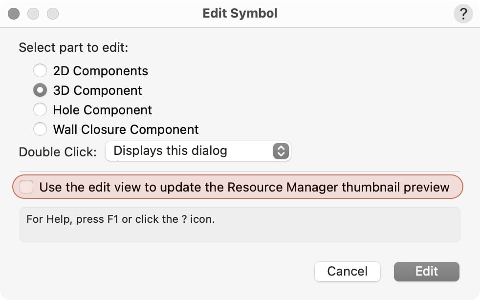
-
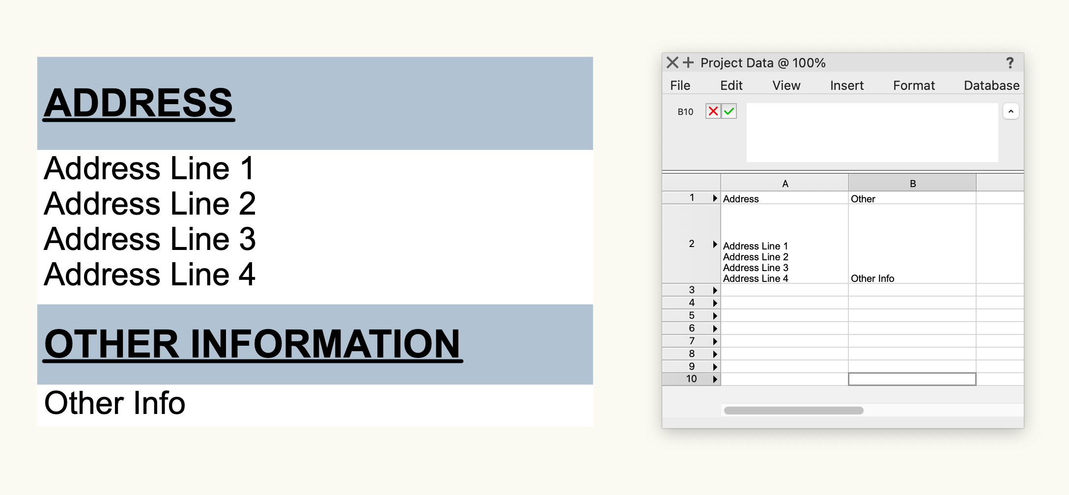
Perhaps it's not a data tag that you need. If you want to show data from a central data base or location, maybe a nicely formatted worksheet would be better. Worksheets can report on other worksheet content so you could set up all the data in one Worksheet and then have another formatted version that reports it in a way that looks good. A Worksheet can be added to the Layout Section of a Title Block, all you will need to do is run the Recalculate All Worksheets command, and the embedded Title Block worksheets will update as well Also, a Symbol could do the same thing.....

-
Have you tried using the Worksheet Formula section instead? I have found that empty fields show no text block at all.
- 1 reply
-
- 2
-

-
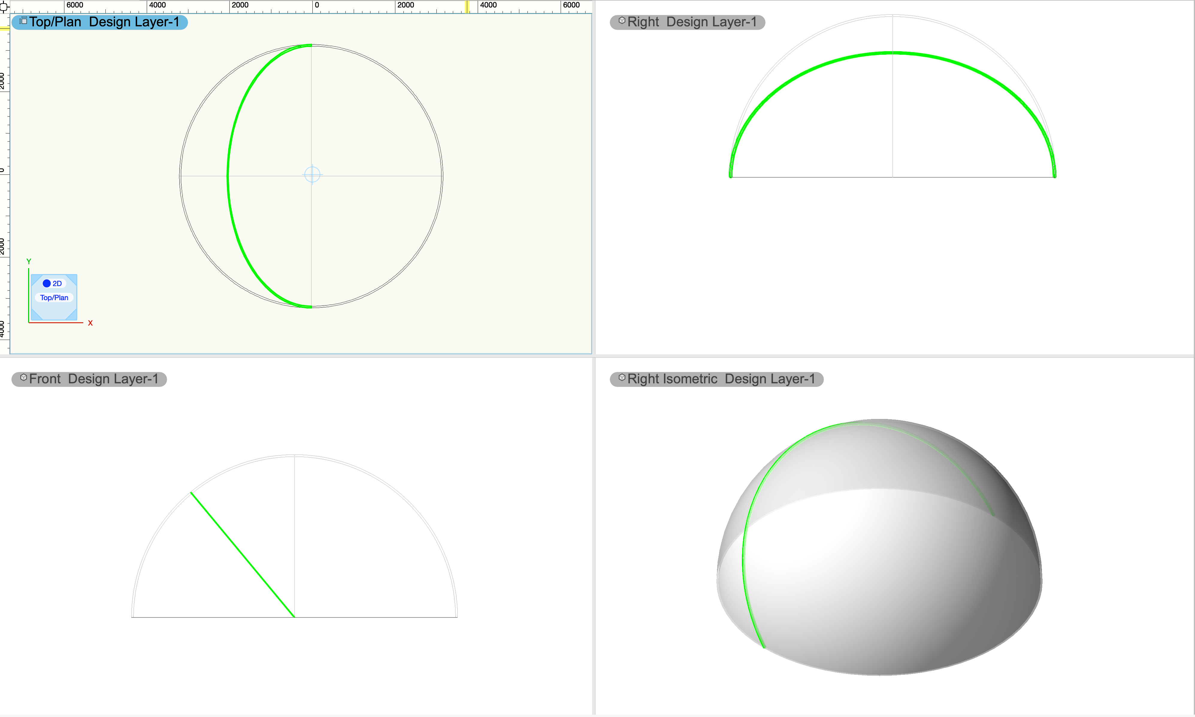
This will give you slices at 3.5° intervals!
-
-
I think the tool you are looking for is the Create Contours Tool. It's in the 3D Modeling Toolset. This will cut incremental slices at a distance on both sides of a line that you draw through a selected object. You need to specify the distance between the slices from the tool preferences button. If you just want one slice, then just enter a value of 0. The result you are left with is a Group of NURBS Curves in the precise shape of the object at the angle it was cut through.

-
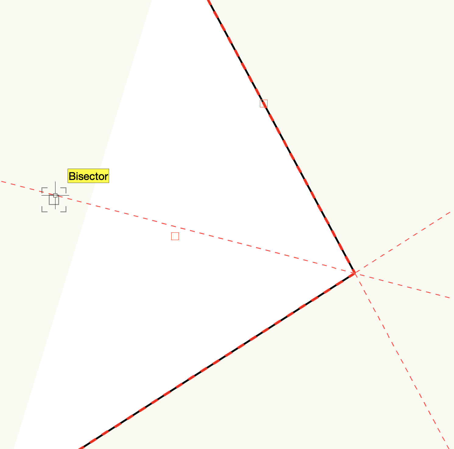
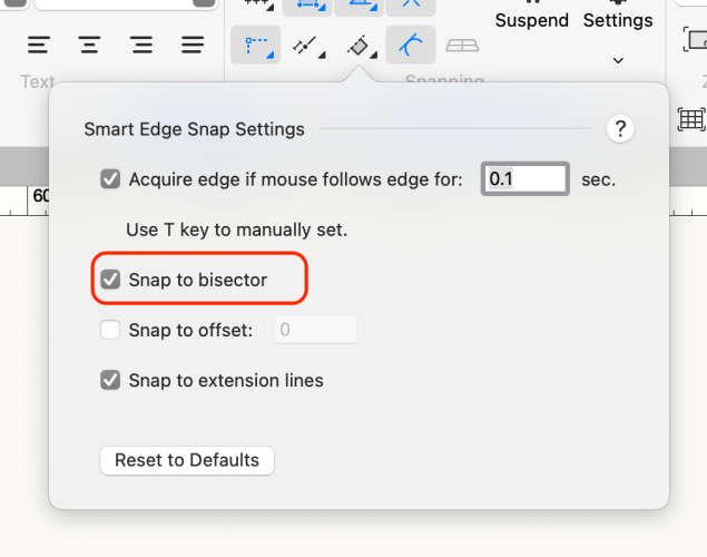
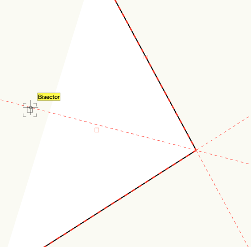
Smart Edge Snap Settings will do exactly what you need.
-
Lighting Device : data presentation 3D view
markdd replied to Antoine D'Halluin's topic in Entertainment
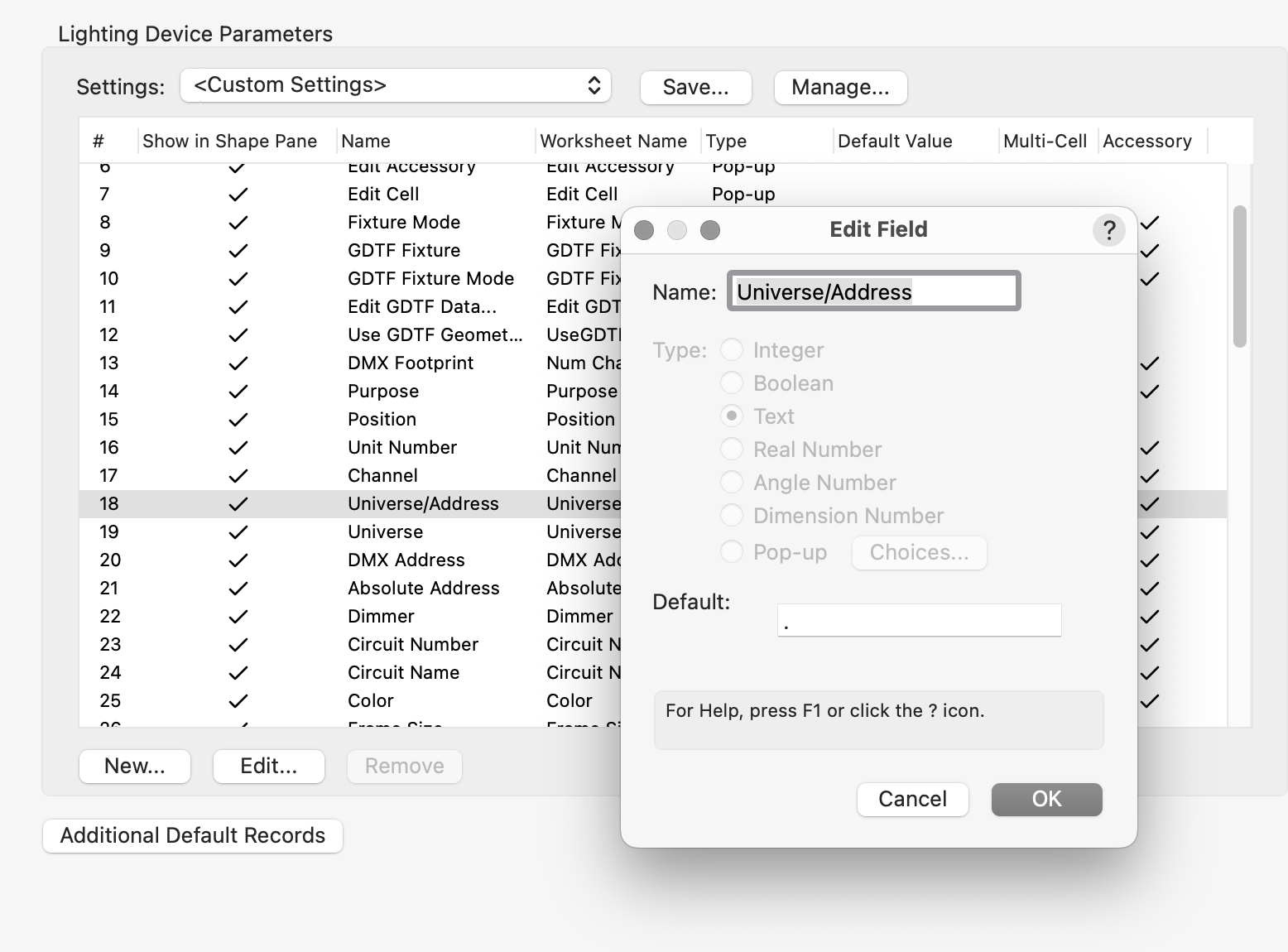
@Antoine D'Halluin With regard to the Universe.Address quandary - There is a MUCH better way that I had completely forgotten about! Go to Spotlight Preferences, and in the Parameters section, you can change the Universe/Address delimiter to "." by changing the default value to "." instead of "/". Double-click on the Univers/Address listing, and you will see this dialog. Change the Default value, and you should be good to go. You need to save the settings in the Settings menu above and check the Save as default check box at the bottom left. This will save a lot of fiddling about with label legends!
-
Deleting Split from Solid Causes Issues
markdd replied to Michael Siggers's topic in General Discussion
Or: if you want to restore the object back to the original, then just ungroup it and delete the plane that is left behind. -
Lighting Device : data presentation 3D view
markdd replied to Antoine D'Halluin's topic in Entertainment
@klinzey is, of course, correct about the ability to add text labels inside Label groups, so forget about my "hack" and go with what he said... -
Great, thanks, Tom. I think that there needs to be a link to this page that is discoverable in either the header or footer of the forum pages.
-
I have no idea! There used to be a link at the bottom of the page. I am a beta tester with my own special link. @Pat Stanford Pat, do you know where the link is for users to report bugs?! I can't find it. Doesn't it need to be easily discoverable by users?
-
Lighting Device : data presentation 3D view
markdd replied to Antoine D'Halluin's topic in Entertainment
Select the Lighting Device, and in the Object Information Palette, change the Pen Style to None. Yes, but it's a hack. Label Legends will not report any data that does not exist within the lighting device. They will also not display Text or any other object for that matter that is not linked to the Lighting Device. SO you need to add the "point" as a field. I have used the Mark field as I have never used it for any thing before. Just place a "." and then make sure that it is reported to the Label Legend. I have enclosed a sample file. All Label Fields are assigned classes. Just change the class color for the Fixture ID or whatever field you use for that information, and you will get the result you need. You need to make sure that Use at Creation is checked in the Edit Class dialog. However, no fields will change color based on their content and Label Legends are coded to not respond to Data Visualization. So, to get exactly what you want, you will need to resort to a Data Tag and Data Visualization. Label Legend.vwx Data Tags are very efficient. With one click, a data tag can be applied to all lighting devices in a viewport. Hope that helps.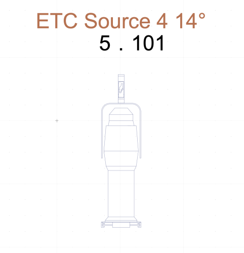
-
@Peter Telleman No problem. Please file bug reports, though; that's the deal! 😀
-
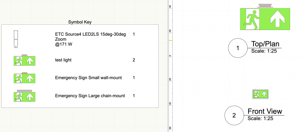
OK, the problem objects are the 2D Polygons in the 3D Component. There is no real reason why you shouldn't do what you have done, as it is definitely catered for within Symbols. But you are using the symbol as a Lighting Device and Lighting Devices don't like 2D geometry in the 3D component. I went back to your original file, removed the Light info record, and then added your Symbol as a Symbol instance within the Equipment Summary Key, and it worked fine. In the Test Symbol, I have changed the graphic to a Texture and also added the 2D Geometry to a Front/Back component so that the Graphic can be seen in a Hidden Line Section Viewport. Here is the file back......Wall Mount small issue (fixed).vwx One thing I have noticed is the file is very large for such a small amount of geometry. That needs to be looked at. It may also be worth filing a bug report on the Equipment Summary Key, as what you have attempted to do is not out of the ordinary, and there is probably something amiss with the way the key is handling the 3D component. You could also file a separate bug report with this file to try and find out why it is so large. I hope all that helps!