All Activity
- Past hour
-
This is something that annoys me all the time. I'd thought it was an intermittent bug but now I see it only happens when there are empty lines at the bottom. This at least gives me a way of making it happen less often (avoid those empty lines at the end). But this behaviour is quite maddening especially when you are editing a lot of text boxes in different positions across a sheet. By the way, assuming you have those empty lines, if you then move the cursor to where you want it using the arrows, it *won't* snap back to the bottom if you first type something in the position you've just moved it to.
-

Mac OS Sonoma 14.4.1 makes VW2024 unusable
bjoerka replied to astephens's question in Troubleshooting
Just updated to Mac OS Sonoma 14.5 At least the page setup dialog now shows again all the pagesizes that are available for each printer. We´ll see what others will report if all other problems are solved with this system update. -

Crop edit not showing objects beyond crop line
Peter Neufeld. replied to MGuilfoile's question in Troubleshooting
You'd better check for outlier objects. If you go to Tools>Origin>Centre Drawing on Internal Origin are there large numbers? If so, are the numbers still large where it says if you proceed the objects are X away from the Internal Origin? If so then you'll need to hunt for the errant objects. If not then click ok to centre and see if that helps. Cheers, Peter -

Need help with a script, for creating symbols from groups
MullinRJ replied to TSG-Sim's topic in Vectorscript
Hello @TSG-Sim, You are quite welcome. The script I wrote doesn't care about a moved origin, so you can use it either way. When you start digging into scripting, it is best if you start with an unmoved origin. Later you can move it, but proceed with caution. Most seasoned scripters avoid making things harder than they need to be. Call it lazy, or wise. Take your pick. Though I can't tell how your origin was moved, it might have happened during a DXF/DWG Import. I believe some options will move the origin and some won't. You might look to see if that caused your shift. Or as you suggest, it may have already been in your template. There are many ways to move it, but no perfect way to isolate how it moved after the fact. If you find it, great. If not, just be aware. Raymond -
Thanks. Looking for something somewhat parametric at this stage though, so that I can fiddle with various options. I've ended up using the legacy "custom stair" tool which allows a sort of ellipse made up of several curved sections joined together. Rather painful to make adjustments to but better than nothing.
- Today
-

VW for iPadOS, please 🙏
Matt Overton replied to PenChiselCamera's question in Wishlist - Feature and Content Requests
Which will then cover visionPro by extension. -

Corner Block Woes - Allow Extra Roll Angle not working as expected.
jcogdell replied to Mike Rock's topic in Entertainment
Hi Mike I'm not sure I'm fully understanding what you are after here, From looking at you file do you mean you want the outer uprights to be orientated the same as the one in the middle? -
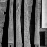
 Hi, See pic below. I draw my line for my visualisation/walkthrough, then when I move into camera view/3d mode, all the plants turn into these black rectangular symbols and now they won't change back. Anyone know the solution? Thanks
-

Need help with a script, for creating symbols from groups
TSG-Sim replied to TSG-Sim's topic in Vectorscript
Raymond you are a legend, thank you, I tested that and that works perfectly for what we need, I definitely owe you a drink for sorting that. I did not know that the user origin was shifted away from 0,0 on that file so the template at some point must have been moved and I have not checked the origin since then. I will make sure my templates are an unmoved user origins going forward, I thought I had used the base metric template from Vectorworks as my starter for all my templates and just put things like title blocks and things like that in so at some point it must have been changed, when I get home tonight I will look through the whole script because it will be helpful to me learning that as well. I didn't even realise functions were the same, I thought you had to use procedures so that is very useful information throughout your code for both learning scripting and doing the work we need. you just saved me a lot of time doing symbols. Thank you, -
There was a problem with the forum Monday morning Pacific Time that appeared to be an excessive load on the server. I have not heard the final resolution, but by Noon PDT the forum seemed to be running normally to me. Just got back on at 11:30PM PDT and it seems to be ok now also.
-
Hi, Thought i should try Datasmith again. All good until i go to plan view in Vectorworks, the Twin Motion says VW has stopped exporting a 3d and you lose half of the model in TM. When you re sinc the file via the datamith Direct link auto sync you get a model without all the textures you placed on in TM. Is anyone else experiencing this? Will have to go back to Exporting in CD4 format. Thanks in advance.
-
Need help with a script, for creating symbols from groups
MullinRJ replied to TSG-Sim's topic in Vectorscript
Hello @TSG-Sim, I was hoping that was the case. It would not be pretty trying to put them together if the separation was arbitrary. Now you're getting picky. 😉 The true answer to your question is "with a good bit more code, and lots of trial and error." I had 99% of the script written and still spent several hours figuring how to move the 2D and 3D parts in unison. It seems easier than it really is. Still, patience prevails, or maybe it's pig-headedness. OK, the script in this file is a bit more complicated, as it uses many 3D commands to manipulate both the view, and the objects, to get what you asked for. I commented somewhat heavily, but it may still seem cryptic. Please don't hesitate to ask what's going on. Grp2Sym test file 2.vwx Raymond PS - One of the oddities I ran into with this file is the User Origin is shifted away from (0, 0). This typically makes simple tasks much harder. If you are going to try improving your scripting skills, may I suggest you start with an unmoved User Origin. After you get comfortable in the VectorScript or Python languages, then you can see how moving the User Origin affects your code. Hint – some commands understand the shift and others don't, and it's not documented anywhere, which makes some people run for the hills. As always, use this Forum often. The help is excellent. -

Problem with "Use Symbol" for 3D rack equipment items
Conrad Preen replied to SSvectorproblems's topic in ConnectCAD
@SSvectorproblems I really would like see that file. At the moment all I have to go on is what you tell me. And it does raise some questions: Are you drawing your schematic on a sheet layer? not a design layer? Again, not on a design layer? seems unlikely because sheet layers are fixed at 1:1 scale. This strikes me as odd because software is pretty much deterministic. What appears to be random is usually not. Obviously the symbol chosen by the Create Equipment command is not the one you wanted but which symbol is it? Knowing this could help. Does this mean that all your devices and their equipment items have the same name? That could seriously confuse ConnectCAD. Let me explain... On a schematic it is sometimes useful to have parts of the same device in different places so that the signal flow is clearer. A classic case of this is patch panels (a.k.a jackfields). You wouldn't want a patch panel to be a single monolithic device with all the various connections snaking to and from it, because it would be impossible to understand the signal flow. The same thing is true to a lesser extent for other devices too. So, in ConnectCAD if 2 schematic devices have the same Name parameter value they are taken as referring to the same real-world device. Equipment Items are used on to-scale layout drawings to show the location and size of devices in the real world. Equipment Items also have a Name parameter which forms the link to the corresponding schematic devices. Equipment names should be unique. However ConnectCAD doesn't do a lot of enforcing - we believe that professional designers know what they are doing. Instead we provide the Check Drawing command that goes thru and lets you know if anything seems amiss. Because often designers will want to create a schematic first and then worry about the layout, we have extra parameters in devices that carry physical device information (dimensions, power, weight) that actually belong to the equipment item. This lets Create Equipment automatically create equipment from devices. Once an Equipment Item exists for a device (same name) then the Equipment Item takes over command of these parameters and on the schematic they become read-only. Now let's talk about symbols. The Equipment Item by default draws a 3D box of the given dimensions (H,W,D) or a rack-mount box if this is set. To allow you to have richer graphics in your layout we have the Use Symbol option in the Object Info Palette that reveals a symbol picker control. Here you can select a 3D symbol of your choice to represent your Equipment Item. Obviously it would be a bit weird if there was a mismatch between the dimension parameters and the actual dimensions of the symbol. So, on the assumption that the symbol has the correct dimensions we set the dimension parameters to the bounding cube of the symbol. If you regret the use of a symbol and uncheck the Use Symbol box the old values are not restored simply because they were not stored anywhere. So the symbol dimensions remain but become editable again. Perhaps that is a little unforgiving, but there is always Undo... So to recap, correct naming is crucial to the function of ConnectCAD. It gives you the flexibility to assign more than one schematic device to the same equipment item. By not playing the role of "uniqueness policeman" ConnectCAD lets you use powerful duplicate-and-modify-rename workflows that leverage the patterns inherent in most systems. Given the little information I have I may be completely off-track here. But I think the above explanation with be useful to others as well, so it is time well spent. Best regards Conrad -
Problem with "Use Symbol" for 3D rack equipment items
Conrad Preen replied to SSvectorproblems's topic in ConnectCAD
@SSvectorproblems Please could you PM a file showing the problem. I will investigate and see if I can reproduce the behaviour you describe. Conrad -
 Hi dear Vectorworks users! We're happy to announce that the beta test for D5-Vectorworks LiveSync starts this week, with the aim of addressing concerns from our many Vectorworks fans. Now, we are excited to invite the initial group of beta users and let’s experience the growth of the Vectorworks plugin together. If you're interested, please don't hesitate to join our Discord channel for updates and discussions. Channel Entrance. We value your feedback and look forward to collaborating with you!
 -
Not marionette, but previous thread about modeling elliptical stair might also be helpful: -B
-

VW for iPadOS, please 🙏
rDesign replied to PenChiselCamera's question in Wishlist - Feature and Content Requests
Link to existing recent wishlist request: -
VW for iPadOS, please 🙏
PenChiselCamera posted a question in Wishlist - Feature and Content Requests
The iPad is the perfect site and travel computer for architects. Except there's no real Vectorworks support. So I always have to lug a MacBook with me too. Please, can we finally get Vectorworks for iPadOS. -
I think you should file this as a bug. I did a little bit of testing, if I have a multi-line text box that doesn't have any extra lines / returns at the bottom, I am able to "click in" the cursor anywhere I choose through either double-clicking or by clicking on the text box while the Text tool is active. But if I do have empty lines at the end of the text box, I can't get the cursor to be anywhere but the empty line without moving the cursor with the arrow keys, and if I click anywhere in the text box after moving the cursor, it will snap back to the bottom empty line. I cannot fathom that this is working as intended.
-
When I click into an existing block of text, if there are any extra lines / returns at the bottom, VW ALWAYS enters the cursor there, instead of letting me click directly into the portion of the text I actually want to edit. I then have to take the time to delete the returns until VW graciously (and generously) allows me the humble privilege to click somewhere else in the text. Look...I think this 'auto-endpoint' could be useful UP TO A POINT (repeat cut-n-paste of info), but when it starts point-blank refusing to anything else, it makes my blood BOIL. (teeth grinding and whole body shaking) How about: first click = auto endpoint (if extra returns) next click = where the user wants the damned cursor to be WITHOUT ANY ARGUMENT FROM VW? ???
-

Vision_About GDTF Blade(Shapers)
haehyeonhong replied to haehyeonhong's topic in Vision and Previsualization
Thank you for your answer. When I tested, all GDTF MODE did not have SHUTTER working. I tried SPOT LIGHT's GDTF provided by ROBE and SPOT LIGHT's GDTF provided by MARTIN, but it was not possible. I've been using VISION since 2020, and I was also upset by this phenomenon. Is there any room for updates? -
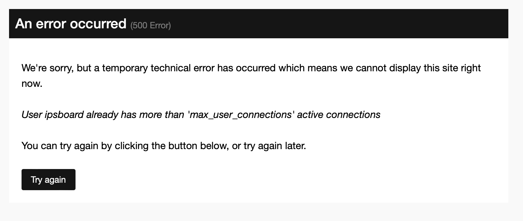
Earlier today, there was a lot of the error in the image below when trying to log onto the forum. Now, later in the western USA, VWX cloud services seems unresponsive while the rest of the internet is doing just fine. Targeted solar flare messing with Vectorworks?

- Yesterday
-
If you want something quick and don't need the skills on an ongoing basis. Then there is the Massing Model tool(s) under site planning that will quickly draw you a building and let you edit it. Sure not great if you care about the look of the building to any detail but ok for planning studies where you want to give a sense of a building.
-
Thanks!
-
Request: Option in the OIP to "Replace" a worksheet.
Matt Overton replied to yasin2ray's question in Wishlist - Feature and Content Requests
Yes, consistency in workflow will always be a good thing.