Jump to content

Peter Neufeld.

Vectorworks, Inc Employee
  • Posts

    387
  • Joined

  • Last visited

Reputation

280 Spectacular

5 Followers

Personal Information

  • Location
    Australia

Recent Profile Visitors

9,128 profile views
  1. Thanks Grant for posting that. A quick search on the forum found this post on the Wishlist - Feature and Content Requests page. I don't know anything about it but there's a link to the developer there. Cheers, Peter
  2. Hello, Yes in this image if you look closely, you can actually see the shadow of the LIDAR scanner and yes the white circle being the area beneath the tripod that it can't scan. If you go to a horizontal view and isolate the points you should be able to get a reasonable Point Cloud just of the surface. Then if you right click on it or go Model>Point Clouds>Extract 3D Loci from Point Cloud you can then get Vectorworks to do that and use the 3D loci as source data for the Site Model/DTM: Note that there are a lot more loci where the tripod is which isn't right so that will need tidying up. I have put in an enhancement request that users can enter a grid setting instead, like 'every 500mm' rather than letting it calculate how it does currently on a graphical colour density basis it seems. Jeff is correct in that communicating with the surveyor or scanning company would be worthwhile. It would seem, but I'm no expert, that your point cloud hasn't been done particularly well. Cheers, Peter
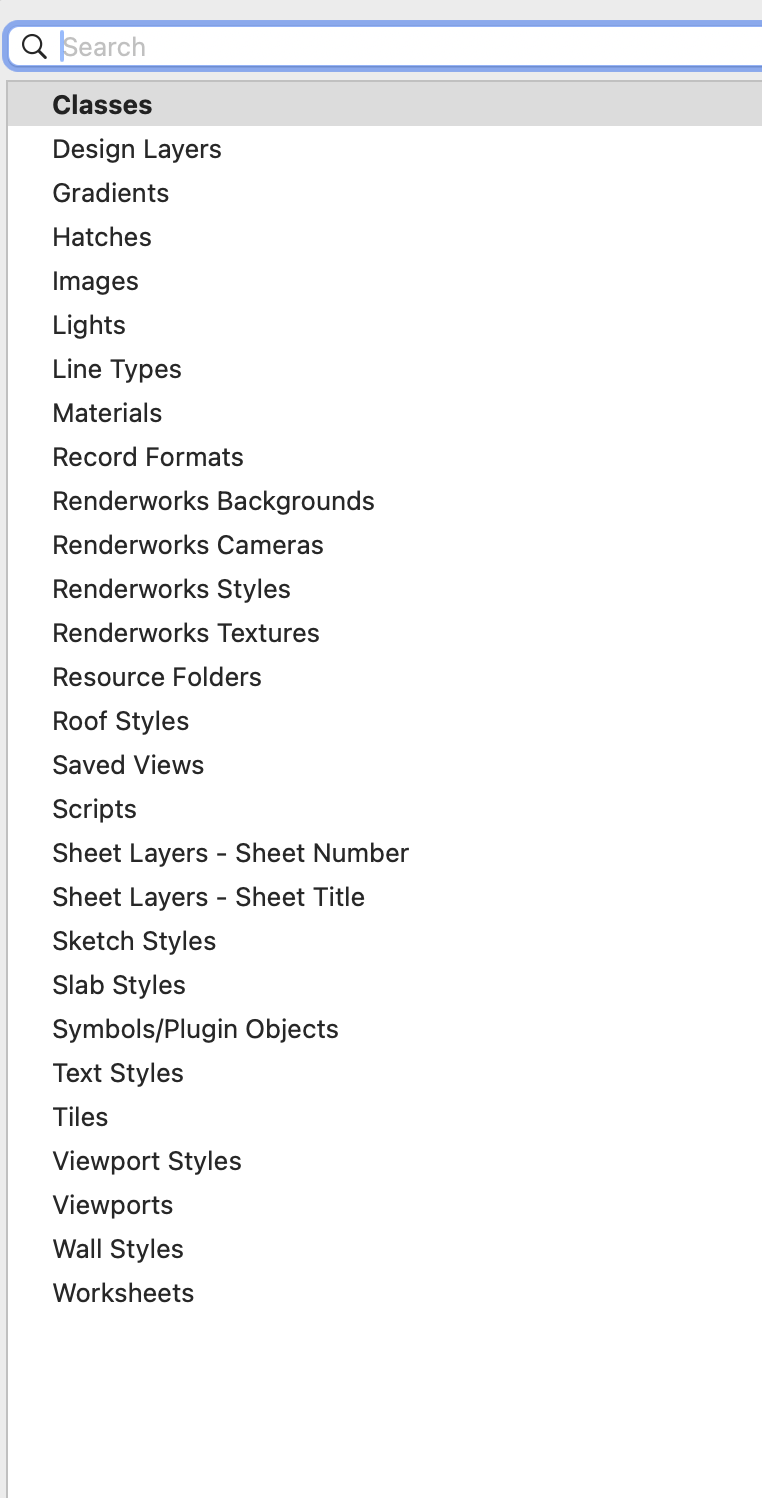
  3. Hello, One thing to consider is that if you bring in an object from an external source - say the Resource Manager that contains classes that are not already existing in the document, they will always be invisible in any existing Saved Views or viewports. While users can control the visibilities of new classes created by the user in the New Class dialogue, you have no control on imported classes. My colleague @Ben Beaumont and I are trying to see if an option for users could be considered. It's tricky because maybe it is better that they don't suddenly appear in everything but we are of the opinion that users generally do want to see the new objects in their existing viewports and Saved Views. Without doubt the Visibilities button in the Organisation dialogue is your fast and efficient friend. Cheers, Peter
  4. Hi Kevin, M3F101. How come the interest in the firmware? Cheers, Peter
  5. Hello, Pat is right when he suggests there is not necessarily an obvious length for a wall. Depending on mitres or curved walls for instance is it the inside or outside and so on. Enclosed is a quick file with two worksheets. One that calculates the length as defined by the wall itself but for only visible walls. The other is for selected walls only. Note for that one the worksheet has to be open otherwise a selected wall will be de-selected when right clicking and recalculating the report. As a resource they can be used time and again. Wall length worksheets.vwx I hope this helps. Cheers, Peter
  6. Hello, I'm not sure if the repair function looks at the Vectorworks Cloud Services app but worth a try. Missing .dll files usually means they've become corrupt and you have to get Microsoft to fix that. This Knowledgebase article should help. It might be a coincidence that you were upgrading Vectorworks at the time. As Pat has said you could try running the uninstaller from the Vectorworks 2024 folder but don't delete your user folder when prompted so that your settings and any templates and so on are preserved and then reinstall. FYI, here is the Vectorworks Cloud Services download page: https://cloud.vectorworks.net/products/ Otherwise please contact your local technical support. Cheers, Peter
  7. This is a bit of an experiment but to follow on from Tom, please try this: Open System Settings and search 'Display'. Click 'Advanced' at the bottom: and then 'Show Resolutions as a list' at the top of the next dialogue: As you have a Retina display you will have a low and a high resolution choice for the external monitor but the numbers will be the same. I'd be interested if you chose the low resolution one as see if that makes any difference. Try switching to the low resolution option: Your problem might be something entirely different but it might be worth a try. As well as trying another monitor type and connection. Cheers, Peter
  8. Hello, If you try another monitor does it still happen? Cheers, Peter
  9. Svobodas!! Great video Mark, nicely done as always and what a great instrument! Cheers, Peter
  10. Apple Migration Manager usually won't work anymore due to Apple's new security. I usually rename my Vectorworks installations (for testing reasons) but if I rename after opening for the first time the next time I try the OS says it's damaged. Ok if I rename before the first open. So this is an Apple thing, not Vectorworks as far as I understand it. Cheers, Peter
  11. Hello, If you plug in an external monitor like the System Requirements page says, you need to consider more Unified Memory. A 16" MBP screen at 3456 x 2234 = 7,720,704 pixels. Plug in an external 4K monitor at 4096 x 2160 and it will add 8,847,360 pixels. That's 16,568,064 pixels in total. Also, 2D geometry can be more demanding than 3D because of things like transparencies, image and tile fills, drop shadows, hatches and so forth. Having said that I have come across users with several external monitors and only 16GB UM and are happy. Cheers, Peter
  12. Here's a quick attempt with minimal words to get a decent result. The original: The result: Cheers, Peter
  13. In that image the 2D locus is beyond the bounds of the geometry. That is, to the right side of the shape. Nothing extraordinary there. Cheers, Peter
  14. Hello, To summarise, there are two rules about Sweeps: 1. Whatever is on the left is the centre of the Sweep. 2. If a 2D locus is part of the Sweep then that becomes the centre. If the locus is within the bounds of the geometry it is unnecessary and won't work because of rule 1. It's always been like that as far as I can recall and is logical. I don't know what you are trying to model but your geometry has different unmatching objects at either end so sweeping from the centre doesn't make sense even if it was possible. With the texturing using the 'Apply to Face Mode' tool, once I enter the group of extrudes it seems to work as expected. Cheers, Peter
  15. Hi Brianna, That is a very good observation about the insertion point. There are three ways that this is controlled: General Preferences>Display>Accelerate Graphics on/off. As above, this turns On/Off the VGM. Document Preference>Display 'Adjust Flipped text'. Viewport>Advanced properties>'Adjust Flipped Text'. It's tricky getting to the bottom of it but I think I've sussed it. If you have the Document Preference>Display 'Adjust Flipped text' Off, you can edit a viewport enter the Annotation Group and enter text and flip it, and it will read ok. Note the insertion point is bottom right. It reads ok because by default the Advanced properties>'Adjust Flipped Text' is on. The VGM doesn't affect this as far as I can tell. When published to PDF, these flipped annotations are produced backwards and not what you see on the screen. I have a bug report about this and it's been hard to work out what's going on without your post so thanks, and I'll add all this to the report. Cheers, Peter
×
×
  • Create New...