All Activity
- Past hour
-
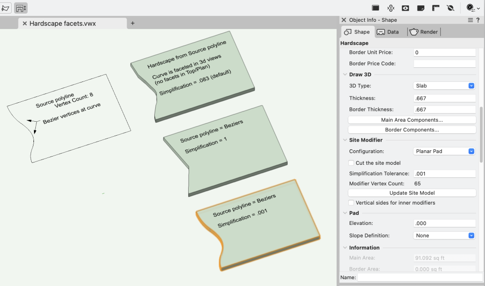
If you change to .001, doesn't that give you a huge number of vertices?
-
Alt + 0176 on a numeric keypad apparently...
- Today
-
 Thanks a lot! You're a mastermind - really! I never came through the idea to choose the basic criteria (of e.g. Channel - 3D) for a dummy report... But it makes sense. Even the result looks strange... This dummy-worksheet lists both types of Series: AISC (inch) and DIN (Taperd Flange) although the profiles I used are all DIN. For Size it's more confusing - 8 sizes are listed: '__size_8' is the one I used (U60) but for example '__size_6' gives 150 x 75 x 18 what is completely wrong. That looks more than a try-and-error-thing (at least for me). At the end I'll find out what is necessary - even it consumes more time than expected - so what's wrong (if any)? one last (???) question: I have different parts of the construction and the record formats are all the same - just with different names (Rack, Frame, Box etc). I made one worksheet for one part of the construction with all the fields the manufacturer needs to know. For example - in the worksheet the formula ='Rack'.'Part' gives the result for all other columns too. Copying the worksheet and change the formula to ='Frame'.'Part' gives no result at all. So I guess there is more 'content' in the worksheet that I can't see, right? cu 😉 Peter
 -
 A_Tak joined the community
 -

Multi-storey building all in one storey - would this work?
Tom W. replied to line-weight's topic in Architecture
Thanks @line-weight. I think it's just the rather convoluted way that VW has designed Stories to work: first you create custom level 'types', then you use these to create your Default Story Levels, then you are finally in a position to put your Story/Stories together by selecting which Default Story Levels you want to include. When you create a new Default Story Level you have the option to associate a Layer with it (see 'Create Layer' check box). Or you can edit an existing Default Story Level + create a layer for it after the fact. It's as if you can come at it (structuring the file) from the Story side of things where the Levels have primacy + Layers are added as part of the level-creation process as + when you need them, or you can come at it from the Layer side + add Levels to the Layers which I think is what you are doing. I have kind of done a mish-mash of both. I like the fact that I can have a Design Layer for (for example) all my furniture, kitchen units, etc + link that layer to a Story in the way that you do + then have access to multiple Levels set to the different floor finish elevations (if I have different thickness floor finishes in different rooms). So I can have all my objects on the same Design Layer but (because they are all symbols) set their elevations in the OIP based on the room they are in + the corresponding Level. Previously I used to set up different Design Layers with different layer elevations + place the objects on the relevant layers. By associating the levels to the Design Layer I can keep the layer + the levels separate i.e. I can have an 'objects' layer + 'laminate floor', 'floor tiles', 'carpet', etc levels. I don't want 'laminate floor' or 'floor tiles' design layers which is what I'd end up with if I created the layer in the Stories set-up. I've probably got all this completely wrong but that's how it looks to me at the moment! I wondered about this too. -
- It is currently working when it is active as the TBB gets reset to update the Total Number of Sheets and Page Number fields. The side effect of this is that the Sheet Number and Title get updated too.
-
What happens when it doesn't work? Do you get an error message? I can't get it to fail. Unless it's two 3D Polys instead of one. I'd probably draw the path as a NURBS Curve (Curve Degree 1) rather than a 3D Poly.
-

EAP, Multiple Planes, Radiused Corners
Ed Wachter replied to Ed Wachter's topic in General Discussion
Fun video! Not to mention informative! Thanks, Ed - Yesterday
-

EAP, Multiple Planes, Radiused Corners
Jeff Prince replied to Ed Wachter's topic in General Discussion
The easiest way to do things is usually the 2D way... ...with some helper geometry to snap to automatic 3d working planes. You just have to draw on different planes and then turn your 2D work into 3D Polys. Here's a video, easy peasy. eap in the sun.mov -
='Channel - 3D'.'__size_1' ='Channel - 3D'.'__size_1' ='Channel - 3D'.'__series_1' The field names might be different if you switch to a different Series. Easiest way to find things like this is to make a dummy report in a worksheet and add all the fields in. Find the columns that have the data you are looking for and then look in the header row for the field name.
-
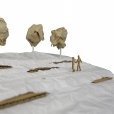
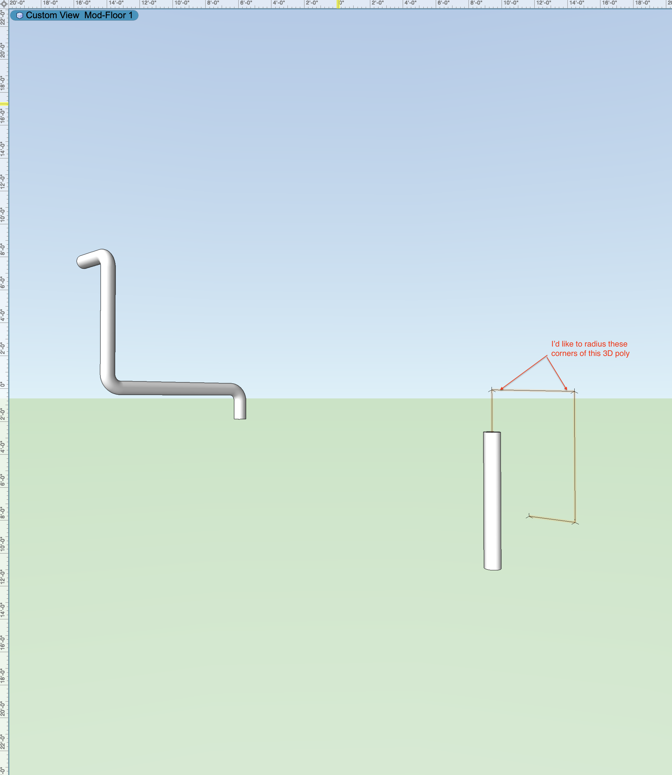
I use extrude along path to make fireplace flue pipes, hand rails, etc. If the path turns out of a single plane, I start with a 3D poly as the path. I often want to radius the corners. Sometimes I can; sometimes I can't. This image shows an extrude (to the left) that worked fine. Now, on the right, I've got my 3D polygon, but the radius ("Fillet Tool") does not seem to work. How do you model shapes like these? Is the Fillet Tool the best tool for this? Thanks, Ed
-
Title Block Setting Updating scale question
Patrick Fritsch replied to MartinFahrer's question in Troubleshooting
Already a better explanation Nokolay...but....this still needs to be more flexible...a lot of wasted time doing something SO tedious. -
Referencing a floor plan while editing interior elevation viewports
Jeff Prince replied to gfyfe's topic in Workflows
There are several ways to go about this. if you are using sheet layers… You can place a viewport of the plan view above your interior elevation. As long as you have “show other objects…” mode active, you can see and snap to that floor plan while working in the annotation space of your interior elevation viewport. If you prefer to work in the design layers to layout your work, you can make a design layer for interior elevations and place the viewports there. Then, you can work in the design layer to embellish your elevations. You can make viewports of cropped portions of the plan and move/rotate them as required to suit your elevation. Personally, I find this to be the fastest method, as you can move between elevations quickly, option/drag to copy elements between them, and arrange your views much easier. Then, you just make a single viewport to your sheet layer for an arrangement of elevations. Vectorworks performs faster too when there are fewer sheet layer viewports to update. -
 Sparq1200 joined the community
 -
I switched my printer driver to a global postscript driver for my Xerox C8030 and it corrected the problem. Good luck VW community! Thanks, HK
-
@tragge8 What happens when you place a summary key in a new drawing? The underlaying file you're using was originally built five years ago. Not that this should cause issues, but it does on occasion. Let me know please.
-
As long as they are image props they should be able to slide under the door 😄
-
Cool! For me it is 25.4 (mm) = 1" I guess your units must be feet? (1/12=0.083) Not the most user friendly value in that context...
-

‼️ CONTENT REQUEST: L-Acoustics symbols
JustinVH replied to Mark Aceto's question in Wishlist - Feature and Content Requests
It is on the list but will not happen until the next major version release. -

‼️ CONTENT REQUEST: L-Acoustics symbols
spettitt replied to Mark Aceto's question in Wishlist - Feature and Content Requests
Slightly nit-picky thing but it would be nice if all of the content could be batch renamed L'Acoustics to L-Acoustics. Would save having to rename things as they are used from the library. -
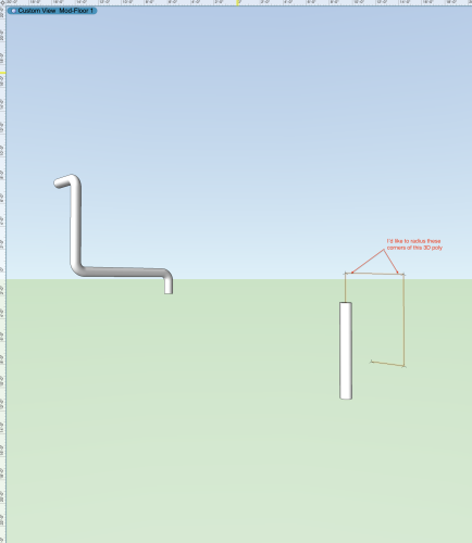
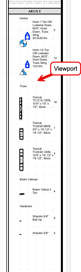
We are hunting a bug and this file helps. For now, I recommend placing a viewport of a summary key in your rigging design layer over the title block area. The Summary key is working as we wish in Design layers. Sorry, no; you can't place viewports inside the title block style. It'll have to sit over the title block on sheet layers for now.
-
I'm also having this issue, panic/crash doors have the hardware on the outside. Now if there its a fire, no one will be able to escape the room.
-
Ahhh! That's it!! @Tom W. - brilliant, as usual. For this Hardscape, the value defaulted to .083. Tried value of 1, which essentially eliminated all the curves and subbed in a single point. And decreasing values. .001 did the trick. The Edit Path window shows the orig source with the beziers intact. -B
-
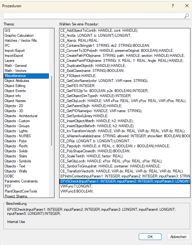
I think the correct way to go about this would be: PROCEDURE xxx; VAR dx, dy, dz :Real; BEGIN dx:= 2; dy:= 4; dz:= 6; CE_TransformVector(FSActLayer, dx, dy, dz); message(dx, dy, dz); SysBeep; END; Run(xxx); I think the function is supposed to take a coordinate and multiply it with a transformation matrix, the return values will be the new coordinate. However I have tried all kinds of objects, layers etc and the output values always remain the same. I don't know how to get a handle to the matrix. There is a bunch more functions in the category but none of them appear to work with matrices:
-
Also try objects on the Screen Plane vs objects on the Layer Plane. Raymond
-
@FMA, Assuming it does exist on your machine, why not try to use it to see what it does? 1) Draw an object. Start simple (line, rect, poly, text, etc.) and work your way up to more complicated objects (symbol, extrude, PIO, etc.) 2) Create a script. PROCEDURE xxx; VAR dx, dy, dz :Real; BEGIN CE_TransformVector(FSActLayer, 1, 1, 1); SysBeep; END; Run(xxx); 3) If it compiles, select one of your objects and run the script. 4) If it doesn't compile, try: PROCEDURE xxx; VAR dx, dy, dz :Real; V :Vector; BEGIN V := CE_TransformVector(FSActLayer, 1, 1, 1); Message(V); SysBeep; END; Run(xxx); 5) If you do get it to compile, try changing the constants for dx, dy, and dz and rerun the script to see what happens. Try (1,0,0), (1,1,0), (1,0,1), (2,1,1); (1,2,1); (1,1,2); etc. 6) Write back if you find anything interesting. Raymond
-
Yeah, I can get it to work but I have no idea what the matrix handle is supposed to be. Maybe it's just for internal use.