spettitt
-
Posts
438 -
Joined
-
Last visited
6 Followers


Recent Profile Visitors
4,087 profile views


-
 Two points: Make a template file set up with everything you could need. Our standard template has probably 20 layers in for 10ish trusses, cable bridges, several LED video layers, lighting floor package, PA etc, plus utility layers to contain venue overlays, datums and other boring stuff. All of our standard viewports have the right visibilities turned on ready - so our rigging plot sheet layer has venue, truss and hoists visible and fixtures hidden. Get in to the auto-classing options in Spotlight Preferences. We have it auto-class truss, fixtures and rigging loads automatically, so we generally don't need to create classes much unless something weird comes up. If you're wanting to get more in to efficiency and automation, have a look at scripting with Python. (I say Python rather than Vectorscript as there is so much more learning resource for it on the internet, and it's great). It seems complicated to people that haven't coded before (it did to me last year when I started) but now I've written a ton of business-specific plugins that do exactly what I want. I have ones that can automatically change class and layer visibility for a new viewport in a few clicks, based on our specific content and classing structure. You need to have a really solid standard class and layer structure first for it to be worth it though. Some people say that it shouldn't get to needing scripting, but our industry has as many opinions as there are people that work in it, and rather than the software having 'one' way of working, it's nice that if you really want to make it work your way, you can.
 -
I suspect you're trying to pull data from both schematic devices and panel connector objects, which won't work. Database rows work on the basis of reporting a given item, and data about that item. You can't pull data about two items in to a single row. Can you post a screenshot of the database builder dialog? i.e. right click the '2' on the left hand side and edit it. I think there might be a way to do what you're trying to do by reporting on the Panel Connector rather than Device, because I think there are some eval functions for Panel Connectors to lookup associated device information. If you can upload the screenshot I'll take a look.
-
Should be relatively possible with scripting, but I'm not aware of anything built in. Would also be applicable to POE power.
- 1 reply
-
- 2
-

-
Sure, attached SimonSimonsCablePath.vwx
-
Thanks Pat, no joy with that though. I can return the number of vertices reliably but that call still just returns placeholder values. However, I managed to achieve what I needed by using vs.Get3DInfo to get the Z height of the whole path. That'll do for my needs. Would still be interesting to know what is inside a Cable Path though and how to access the point data. Ungrouping the PIO produces a generic solid that appears to be an extrude-along-path sort of thing.
-
Hello, I'm trying to find via script the elevation change for a Cable Path object. I can get the x and y OK with Get2DPt, but there is no Get3DPt in the function ref? I've tried GetPolyPt3D, which appears to just return a placeholder number e+100 number, maybe because the cable path isn't a poly. import vs def get_path_elevation(h): path = vs.GetCustomObjectPath(h) end = vs.GetVertNum(path) p1 = vs.Get2DPt(h, end) p2 = vs.Get2DPt(h, 0) p3d = vs.GetPolyPt3D(h, end) x, y, z = px vs.AlrtDialog(f'{end} - {x}, {y}, {z}') vs.ForEachObject(get_path_elevation, "INSYMBOL & INVIEWPORT & (PON='CablePathObject')") Is there a secret Get3DPt hidden away somewhere? Can't see why it wouldn't exist? Thanks
-
Just to add my 2p of something that I think might be relevant here. Not sure if you were thinking of this as part of your product, Sam, or just helping out Cookie. It sounds like would be in your plans anyway, though. Traditionally, breaker width has been the traditional 18mm DIN module standard in the UK, or multiples thereof. But recently, StageSmarts distros have become popular, which use CBi QF17A devices that are 1.5 modules wide. Also, the grouping varies - INDU 72 Ways often have groups of three. So, if there were parameters for Device Width (mm) and Device Grouping (integer) that would probably give it the broadest appeal.
-
Maybe try vs.ResetObject(h) If not, that's pretty much the gamut of reset options, so it might not be a reset issue.
-
vs.SetObjectVariableBoolean(h, 1167, True) This will reset handle h. For all PIOs of a given type, you'll need to loop through them or vs.ForEachObject loop through them.
-
I don't think the built in automatic numbering tools will do exactly this but the Spotlight Numbering tool can do it.
-
Thanks Nikolay - sorry for the slow response, busy week. I think #1 would be possible to manage in a script now that I know, but #3 might introduce some unknown. It's a relatively low priority efficiency script compared to others, so I might put this one on the backburner unless someone starts really asking for it, in which case I'll proceed in context of the above. Thanks!
-
Thanks Pat. So it looks like I need a script that counts records that start with 'Revision', rename them all +1 and then store my new data as -1. I will give it a go!
-
As a daily user of both Fusion (no 360 anymore) and Vectorworks, Fusion does indeed do lots of things that are geared towards the assembly of products rather than a more general CAD platform like Vectorworks. The biggest thing probably being the browser/tree - where you can visualise the component/assembly structure of your design - seeing the bodies, components and subassemblies within your assembly, which is something that VW just doesn't do. It's a typical feature of any of the design platforms from the 'Product Engineering' sector - Inventor, Solidworks, Fusion, Catia et al. It's just a different sector from more general design CAD like Vectorworks, AutoCAD etc. All it is is a UI element that would show a tree of your used Symbols, what Symbols they contain and what primitives are within then...you've given me an idea now 😉 The other thing is the historical modelling element. Vectorworks does kind of do historical modelling, but it's a baby version compared to Fusion, and you can't really 'see' the history like you can in Fusion. When you're developing a complex design with hundreds of components, you sometimes need the ability to say 'right, that's OK, but make the whole thing 10mm longer' and not have to go and move/edit lots of stuff - just change one parameter and everything recalculates/redraws. Also, quite a lot of assemblies use motion of joints and computing of contact. I'm not saying Fusion is 'better' than Vectorworks at all - they come from different sectors. I'm actually trying to move modelling tasks to Vectorworks unless they need to be in Fusion. Building a historical parametric assembly with animated joints in Fusion is quite complex - I often say that I get 'Fusion Fatigue' if I do a day in it. But I do think that some of the features from that sector of software platforms could really improve Vectorworks and maybe even draw some users from that market. I might put a few feature requests in. - Browser/Tree - Better display/insight of historical modelling - Joints with constraints and motion (Before any of that though, it just needs to walk before it can run and at least handle a STEP file properly, my request of which hasn't moved yet...)
-
Has anyone scripted the process of adding a new revision to a given sheet? I can GetRField of revision numbers fine, and I can SetRField for any 'normal' fields, but I'm not sure how revisions work given that it retains the history of previous revisions and their data. I know it's a hidden record field for the revision data, but I don't know how to add a 'new' revision on top of the entries that are there. Thanks
-
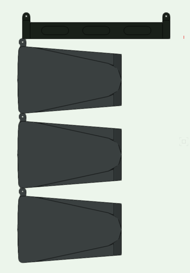
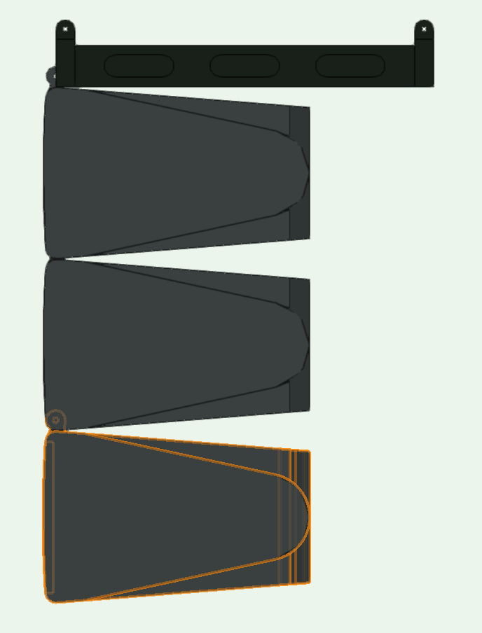
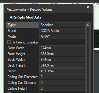
Coda Audio - library error
spettitt replied to spettitt's question in Wishlist - Feature and Content Requests
Yes, I wouldn't remove them, just change the record value so it builds accurately. Front Height as stock: Front Height reduced by 40mm: Tab still present, but nested within the box above so it can be pinned, as per real life.