symo
-
Posts
107 -
Joined
-
Last visited
-
Hi All. Many thanks for your responses. I have increased the font size to 300pt and this has fixed it. @Scott C. Parker I cant see the conversation you shared as I get "Sorry, we can't show this content because you do not have permission to see it". But Im Ok with the current work-around. Cheers Symo
-
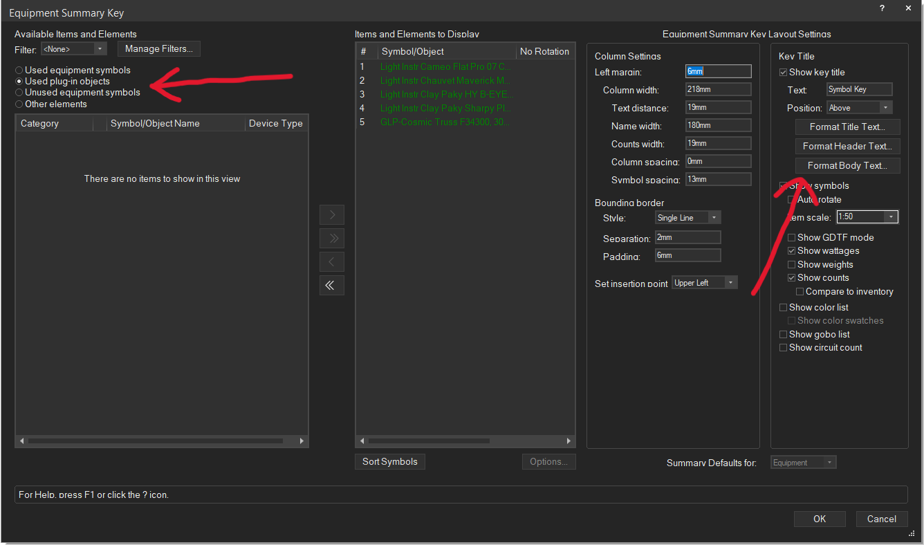
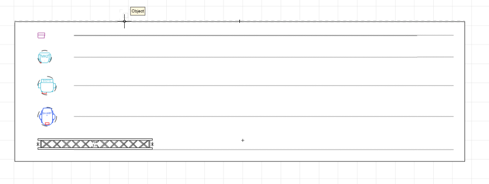
Hi all Im not being able to show any text in the new 2024 Equipment Summary Key Tool. Heres what it looks like: It makes no difference whether I choose "equipment symbols" or "plug-in objects". Also, I have selected Arial for Title, Header & Body text. All classes are visible. Would love to know if there is a work-around for this. Cheers Symo

-
Many thanks @markdd for that very helpful video, much appreciated.
-
Thank you everyone for the very helpful responses. I can see now that the EAP command isnt the best way to go about my 3D shape.
-
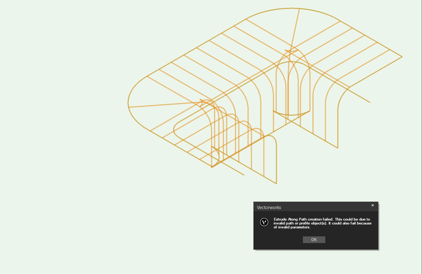
Hi All Im having a lot of issues trying to recreate this kind of shape using the Extrude Along Path Command: I first start by creating NURBS curves for profile and path. Profile on the left, path on the right. I start by creating polylines, then convert to NURBS: I then select both NURBS curves and select the Extrude Along Path command, but this normally fails: I try to rotate the path NURBS curve so that it resembles the shape I want but this fails too. Please let me know what Im doing worng, or if theres is a better way to do this. Cheers in advance. Symo


-
Truss defaulting to 3D symbol in plan view in Spotlight
symo replied to symo's question in Troubleshooting
Brilliant. A great reason to upgrade. -
Yes you can but Im trying to streamline the process of having to: Edit 2D geometry for each symbol Change all 2D sub-classes Repeat for 3D geometry When doing this for a whole series off trusses for example, this can get mighty tedious!
-
Truss defaulting to 3D symbol in plan view in Spotlight
symo replied to symo's question in Troubleshooting
Many thanks Jesse. Do you know if this issue has carried-over into V2024? -
Truss defaulting to 3D symbol in plan view in Spotlight
symo replied to symo's question in Troubleshooting
Hi @markdd I tried with a few different truss symbols and it happened with all of them. -
Hi @Mark Aceto I actually tried that and found it was fine if the new class didnt already exist but wont let you re-name to a class that does exist.
-
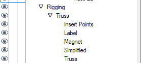
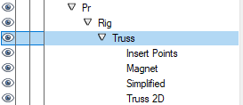
Hi @Mark Aceto I have the automatic classing select as you suggest but Im wanting to update the sub-classes of the truss in order to conform with my own classes. For example, the default class assignments for truss objects are: This is how I like my truss sub-classes to be assigned: Cheers
-
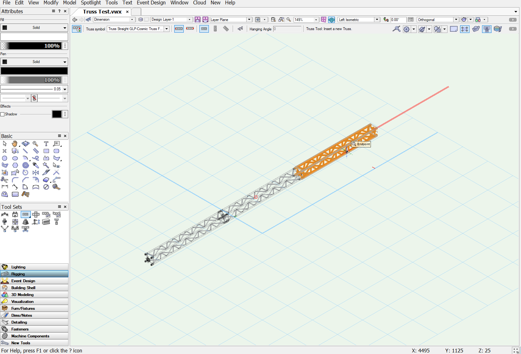
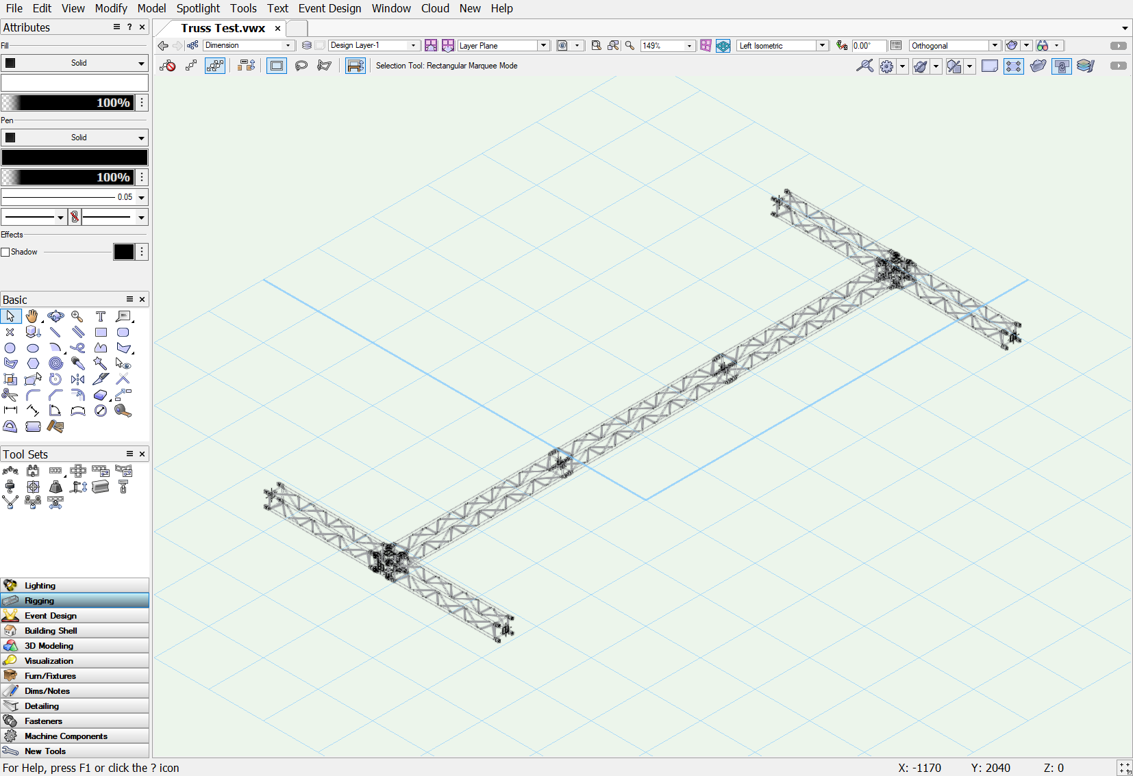
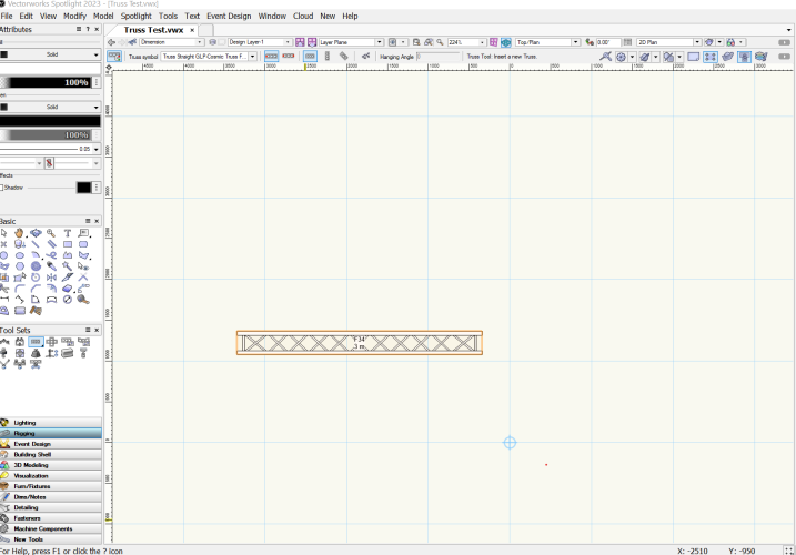
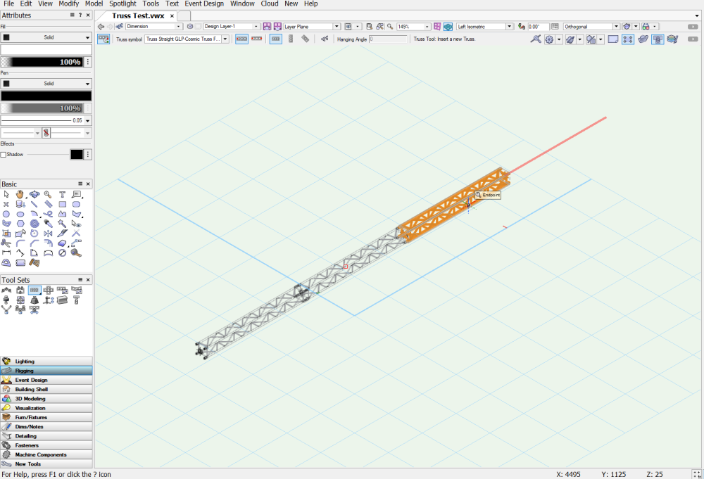
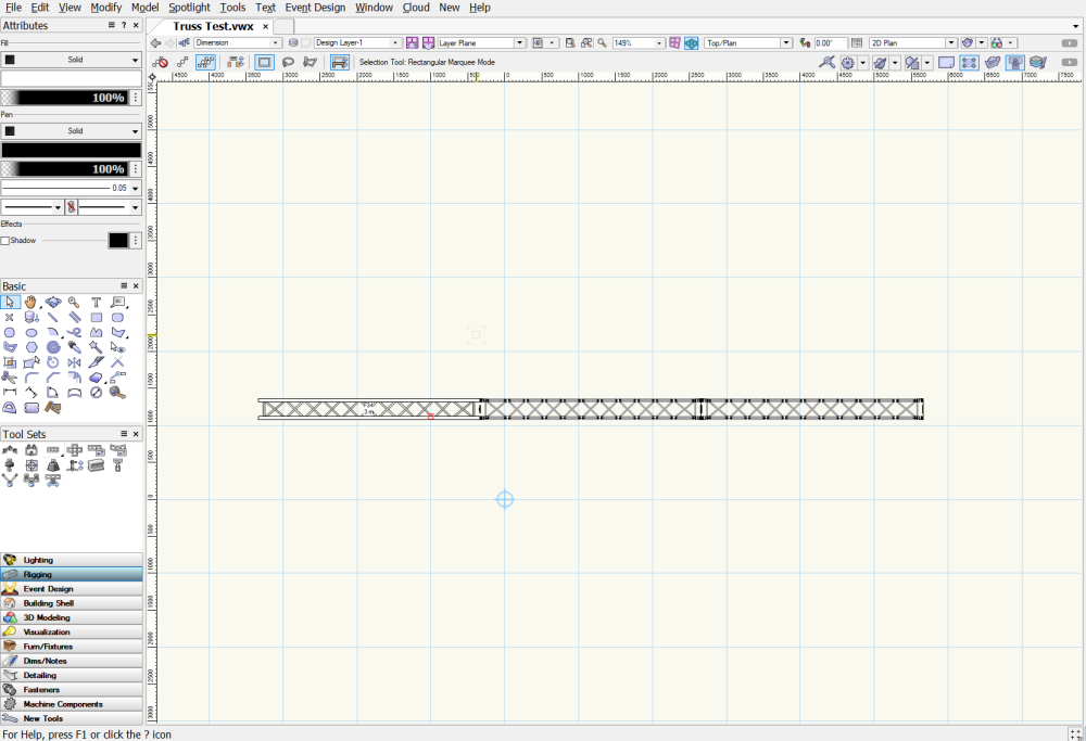
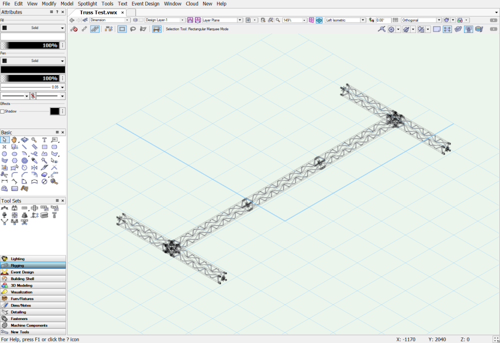
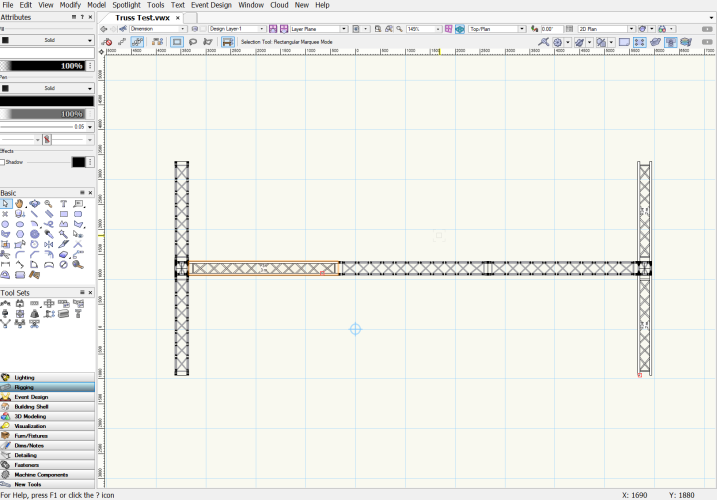
Hi All Im experiencing an issue when I insert truss objects when I switch between Top/Plan view an Isometric view when inserting the truss. This happened in a blank template and using truss symbols from the Vectorworks libraries. I first insert an F34 3m truss section in the Top/Plan view and it shows as expected: Then I switch to an isometric view to continue inserting the truss: Then I switch back to the Top/Plan view and the truss inserted in an isometric view only shows as a 3D symbol: When I add more truss symbols in the Top/Plan view, I get a mix of 2D and 3D symbols: The obvious work-around is to select Draw 3D Only in the OIP and this shows everything as a 3D symbol but this means I cant show the truss labels. It seems that something is horribly broken with the truss tool. Cheers
-
Is it possible to run a script to re-assign classes in a hybrid symbol? What I would love to do is re-class truss and lighting symbols in spotlight so that they conform to my class structure. Im having to do this manually at the moment and it gets tedious very quickly when having to do a new series of truss, for example. Of course, once I do this - I save all re-classed symbols into a favourites file.
-
Hi All Is there a quick way to re-assign the classes of newly-imported symbols? Im thinking that there might be a script that can do this - although its something Ive never done. For symbols that I use often, I save them in a favourites file with everything re-classed. This gets a little tedious when I need to use a new type of truss at various lengths, and having to manually re-class everything. It is mostly truss and lighting symbols in Spotlight that I would like to re-class. Do this in batches would save me a lot of time, if possible. Cheers in advance.
-
@markdd All makes sense - many thanks