
Tony Kostreski
-
Posts
194 -
Joined
-
Last visited

.thumb.jpeg.48a6fdc44e48c98b8e1b507e86e57e95.jpeg)


Recent Profile Visitors
3,348 profile views


-
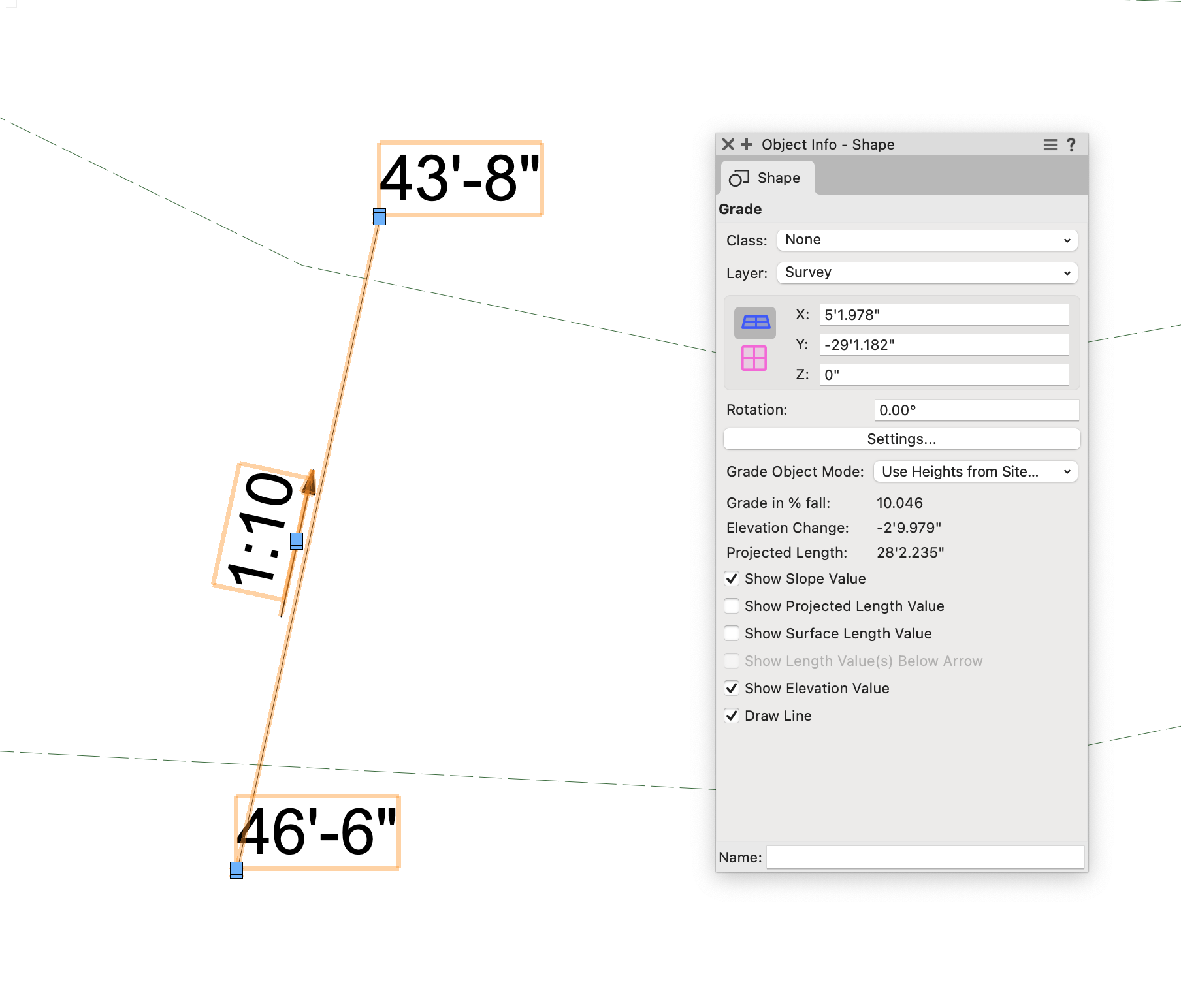
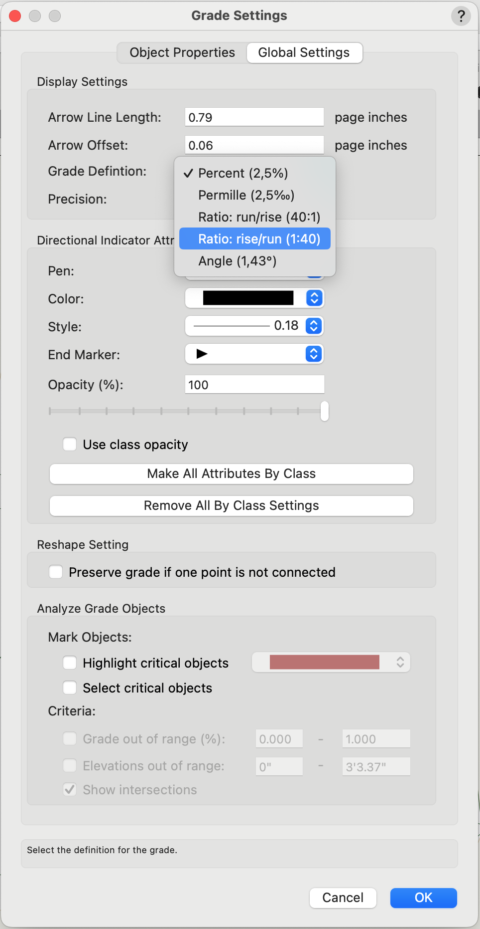
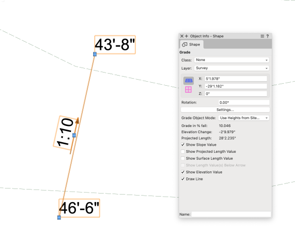
@Amanda McDermottYes, you can use the Grade Object as @Tom W. suggests. Go into the Grade Settings and under Global Settings you can adjust the Grade definition to Ratio: rise/run and also set its precision so you do not have decimals.
-
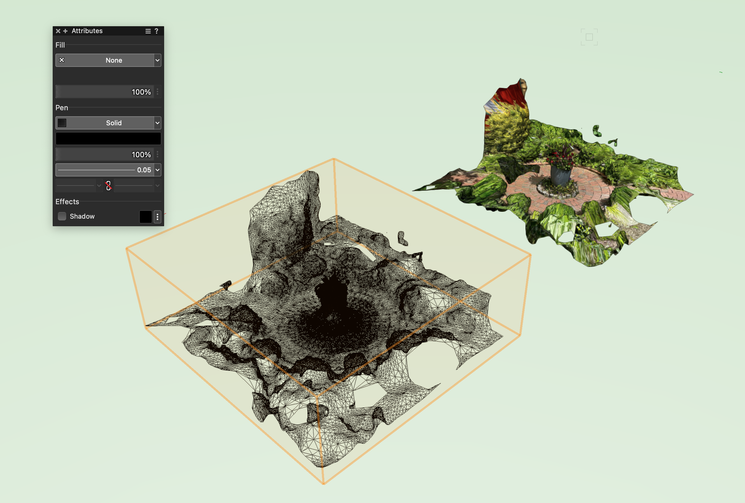
 Yes, you can! I found success with taking anywhere between 50-70 photos. When you process it on the cloud you can use use a reduced output so the entourage elements can stay low between 2-3 mb per model.
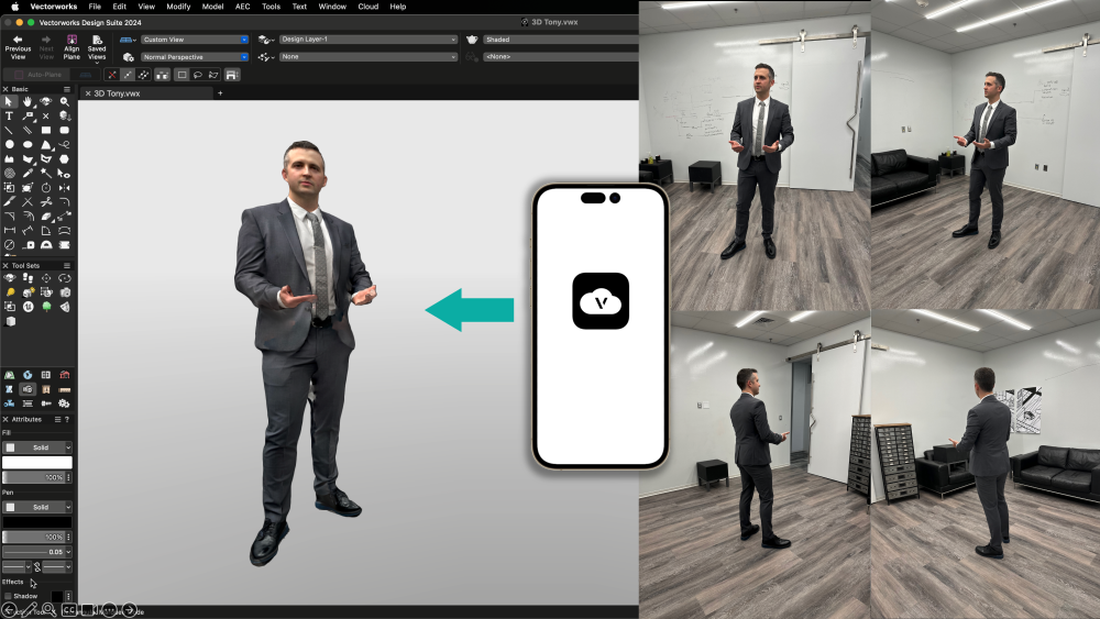
-
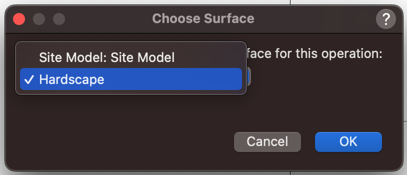
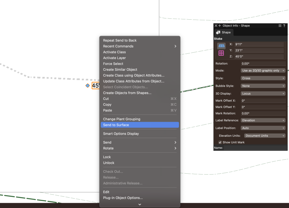
@col clipper Thanks for bringing this to our attention. I'm going to discuss this internally to see how we can improve this behavior. In the meantime, if you set the Stake Objects to "Set as 2D/3D graphic" > right-click > Send to Surface and then select Hardscape instead of Site Model, it will follow the top of the Hardscape object. You just need to make sure if any changes occur you resend the Stake Objects to the surface of the Hardscape.
-
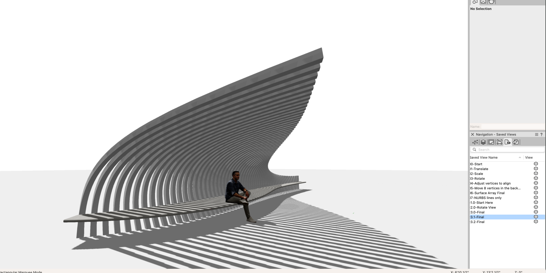
Hi @Kaare Baekgaard, Yes NURBS objects within Surface Arrays are quite flexible. I'm glad you've discovered adjusting U/V degrees. For anyone interested in seeing how the Shade Sculpture was created, I've attached the file used to create the video. Make use of the saved views to see it develops 😉 . In my example, I used 6 NURBS surfaces to form a cube as my "Array Item". You can certainly use one NURBS surface the way you described, ungroup the Surface Array and add an extrusion to the resulting surfaces. Hope this helps! Tony 2024-Shade Sculpture.vwx


-
Hey @JonKoch, Make sure that there is a 'fill' associated with the mesh object. If your fill attributes are set to 'none' prior to import, it will pick up those attributes and look like it's in wireframe. You can always select the mesh object and apply a fill to it. Hope this helps!

-
Hi @burgcj, You can certainly place stake objects manually if there aren't too many but if you want more of an automated way you could use a marionette script as @Nico_besuggested. It looks like you have an object representing a spot elevation (x) and a text value next to it. The following Marionette is quite valuable to automatically place a 3d loci on the (x) marker and use the text value for it's "z" parameter. Instructions: Use "Test Proximity" to make sure the text value is pointing to the right marker (x) Use "Text to 3D Loci" for placing a 3d loci on the marker (x). The "z" value will automatically use the text value pointing to it. I covered this in a webinar https://university.vectorworks.net/course/view.php?id=2434 you can fast-forward to 22:30
-
Test Proximity and Text to 3D Loci
Tony Kostreski reviewed SBarrettWalker's file in Marionette - Networks
 This will save designers a lot of time when creating site models from 2d spot elevations. Instead of manually placing stake objects and inputing the "z" elevation, this will do it automatically by grabbing what's written within a text box and embedding it into the "z" parameter of a locus point.
 -
Way to polyline fill the main area of a hardscape?
Tony Kostreski replied to littlemxman's topic in General Discussion
@Tamsin Slatter suggestion is a great one. If you are looking for quick numbers, you can also look under 'Information' in the Object Info Palette when the hardscape is selected.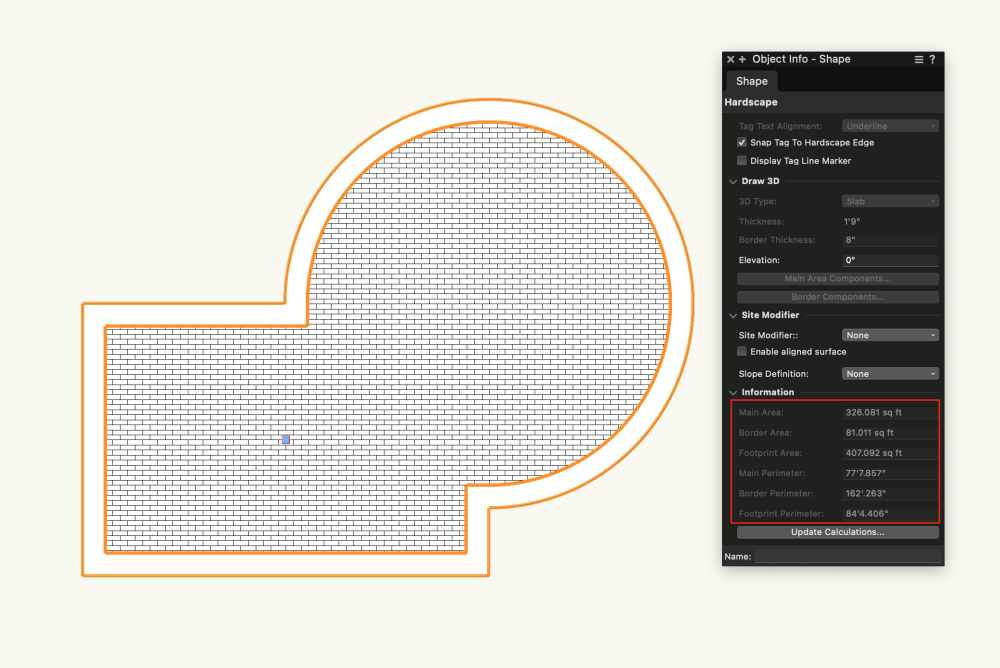
-
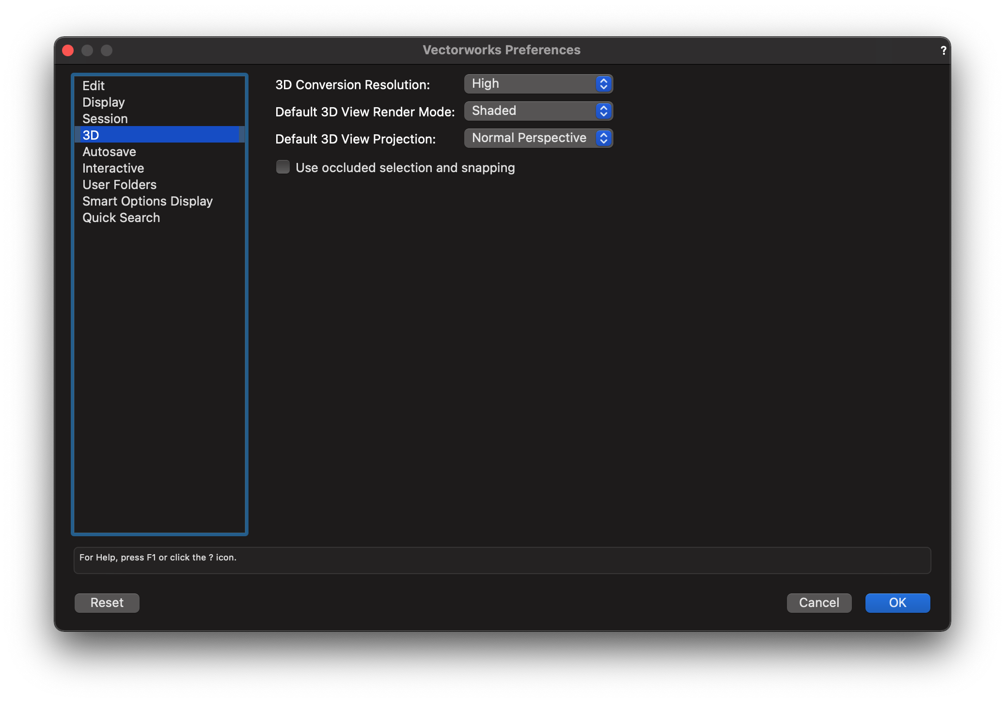
@Paul Nare you viewing this in wireframe? If so, switch to "shaded". You can change your default Vectorworks Preferences for 3D display to always show "shaded". If you just want to toggle between wireframe and shaded, hit the "teapot" on the top bar in between where it says "orthogonal" and the "glasses" on your screen.

-
Hi @Paul N, If you are in Vectorworks 2022, I would suggest checking out the templates. Select File>New>Landmark(Imperial or Metric). This has some initial design layers you can make use of and you can remove/add where necessary. They are stacked so that they appear how you would expect on a drawing set. Feel free to rearrange the stacking order to fit your needs. For the CAD survey file, since you imported it directly, you should be able to edit any and all geometry and symbols (blocks). Make sure your "classes" are set to "Show/Snap/Modify others". I recommend when importing a .dwg file that you select 2D/3D geometry so that if the contours are already elevated they will import as 3D polygons and you can make use of that to generate a site model. "Survey Input" is used for importing an .xls file (spreadsheet) so I would not use that for what you are doing. Place hardscape objects on the "hardscape" design layer, irrigation on "irrigation" layer, etc.
-
Sheet Layers missing in navigation pane
Tony Kostreski replied to NickSolyom's question in Troubleshooting
Looks like your filter is set to <Recently Used Layers>. Switch this filter to <All Layers>. -
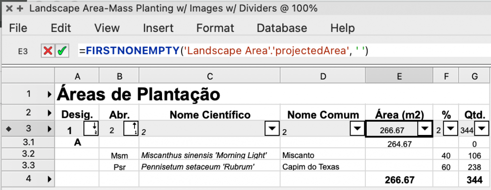
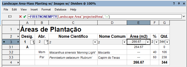
Hey @jpccrodrigues, try this or this Also attached vwx file. Hope that helps! LANDSCAPE_AREA_WORKSHEET.vwx
-
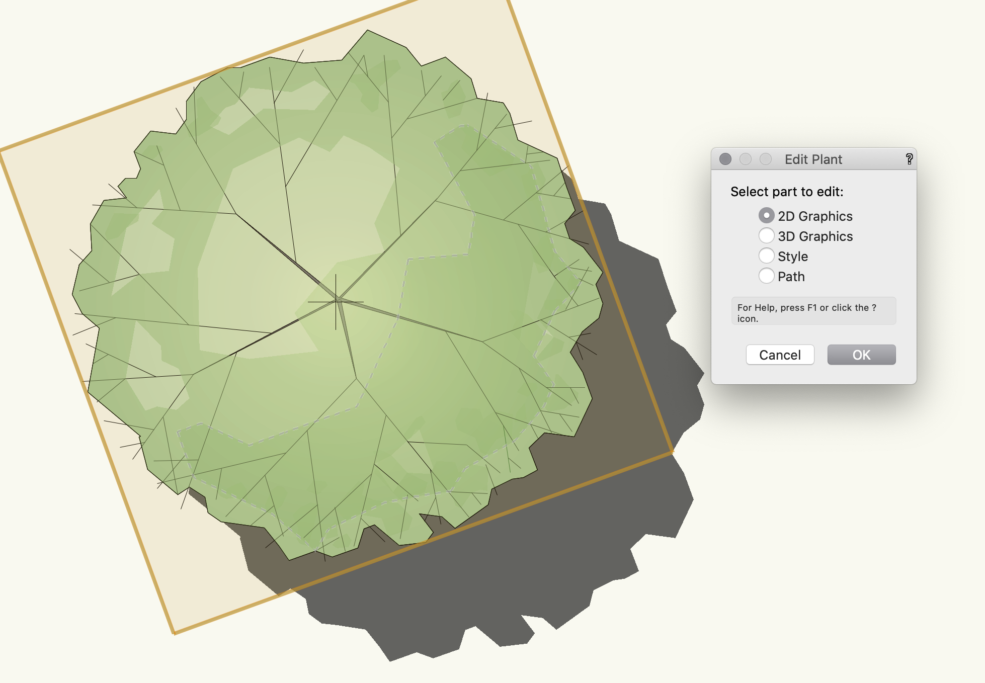
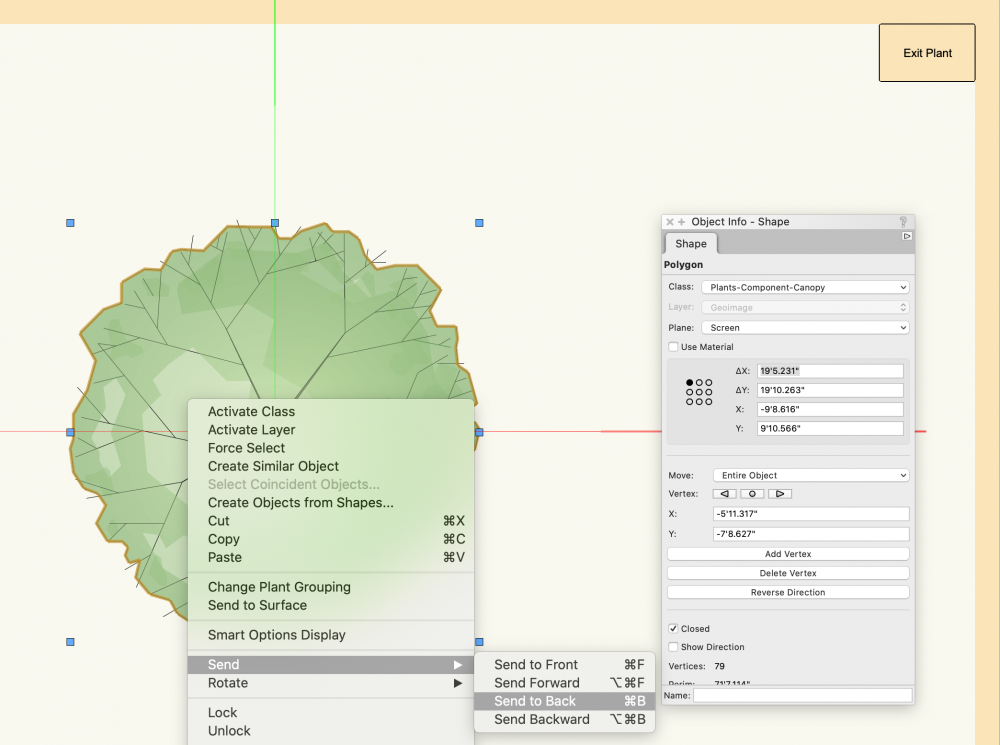
Hi @DSmith2300, just want to confirm the 2D linework of your plant. The plant shadow mimics the geometry that's furthest back. If you're using Vectorworks sample plants, they should be organized correctly with a shape either on the Color Fill or Canopy class behind all other geometry. If the class that this geometry sits on, Plants-Component-Color Fill (or Canopy), is off, so will its shadow. To confirm, edit the 2D Graphics and make sure the geometry you want to mimic a plant shadow is sent to back. Hope this helps!

-
Hi @Ned Daugherty, I'm curious if this just has to do with the resolution of the image. The background will display a preview and because you are zoomed out quite a bit, it might be displaying a lower res image. Once you place a geoimage it will use the default resolution of 1024 pixels which is perhaps higher than the resolution. Try testing out changing the resolution higher or lower and you will notice the image changes, grabbing different images from the server based on your input.
-
Site Plan - Creating Topography from points
Tony Kostreski replied to MaltbyDesign's topic in Architecture
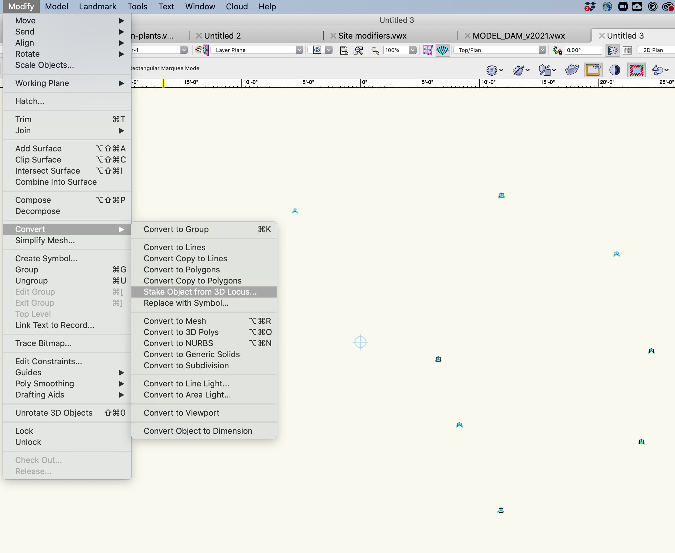
@hchen4If you are referring to 3d Locus points there is a command under Modify>Convert>"Stake Objects from 3D Locus"