
jpccrodrigues
-
Posts
134 -
Joined
-
Last visited
6 Followers


.thumb.JPG.95d0d28345a2bda255e1e6fe74b8be2b.JPG)

Recent Profile Visitors
2,928 profile views


-
Same experience. Phyton script to lay a drop emitter for each plant (a very common request in the forum...). Never worked... Anybody tried to create a Marrionette script? Just curious to see if works or not.
-
-
Rendering Problem! why the model looks like this.....
jpccrodrigues replied to lixinpm's topic in Site Design
Having Georeferenced files is precisely that: having drawn elements referred to a certain datum, usually large kilometers away. If you move the internal origin, you compromise the position. A common way to verify that is the geoimage tool. You need to determine the datum, import the file and, if everything is correct, you get an accurate image. But if you change the internal origin of the file... The relative position changes and the image is moved as well. Considering this, would you keep georeferenced files or keep the drawn elements close to the 0 0 0? -
Ohhh the dwf export problem... Two words: A NIGHTMARE The link is about 3d dwf. I think the topic is about good old normal 2d dwf. But I can name more problems: Classes turned off that appear Classes turned on in the expiry that doesn't appear Worksheets in annotation mode that shirk (if you have the viewport 1:200, you need to scale in autocad the worksheet 200x,or leave it "free" in the sheet) Patterns and images gone Transparencies gone. If concrete examples are necessary, I can upload. It's an old topic, so frustrating to lose hours and hours to correct stupid graphical things when everything is modeled... And then see archicad (not to name revit for obvious reasons) being able to export clean and beautiful drawings...
-
Rendering Problem! why the model looks like this.....
jpccrodrigues replied to lixinpm's topic in Site Design
This has any relation with Georeferenced files? Always had this question... -
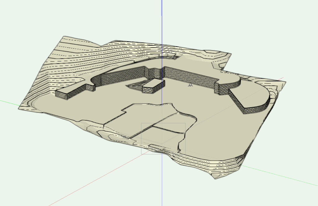
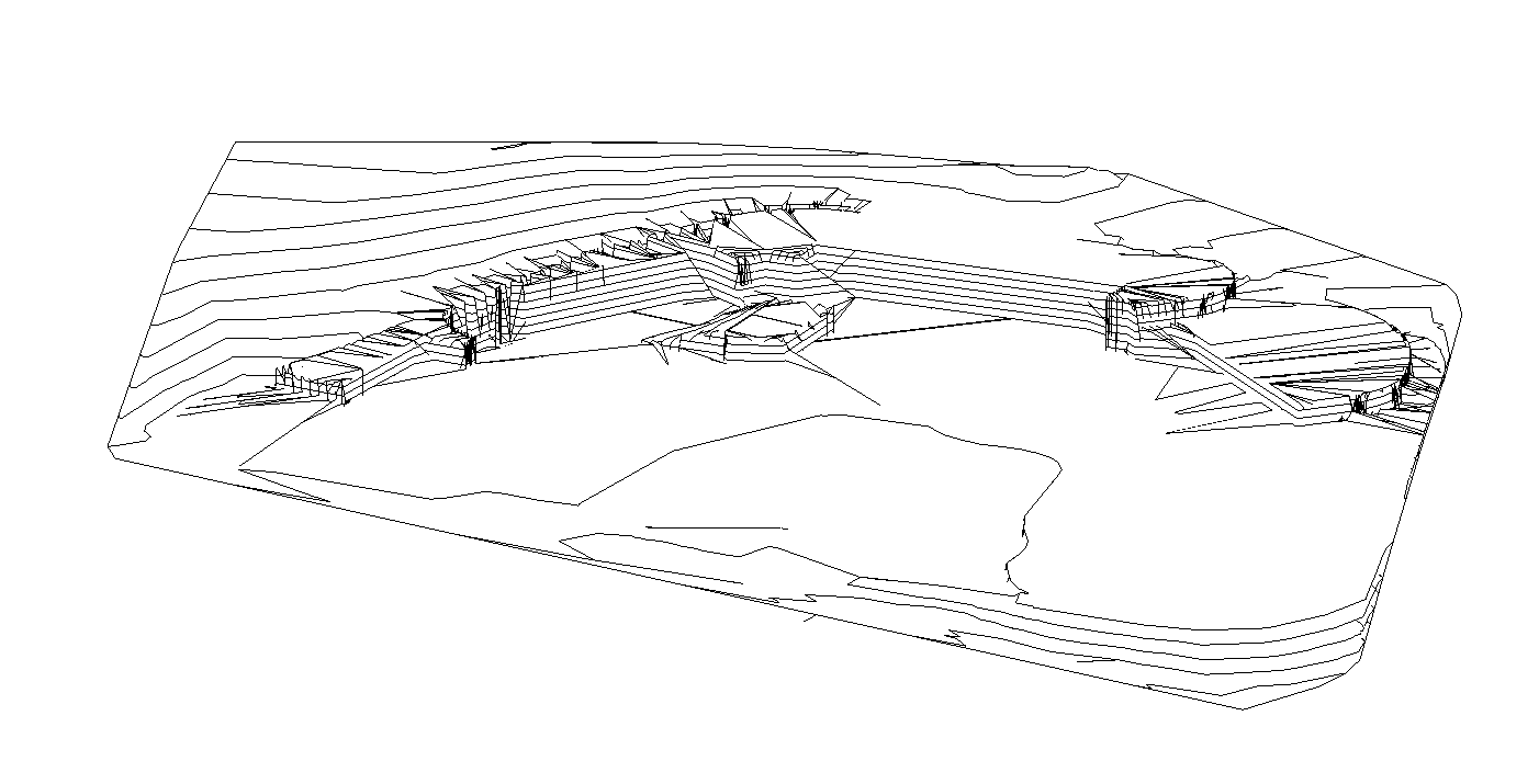
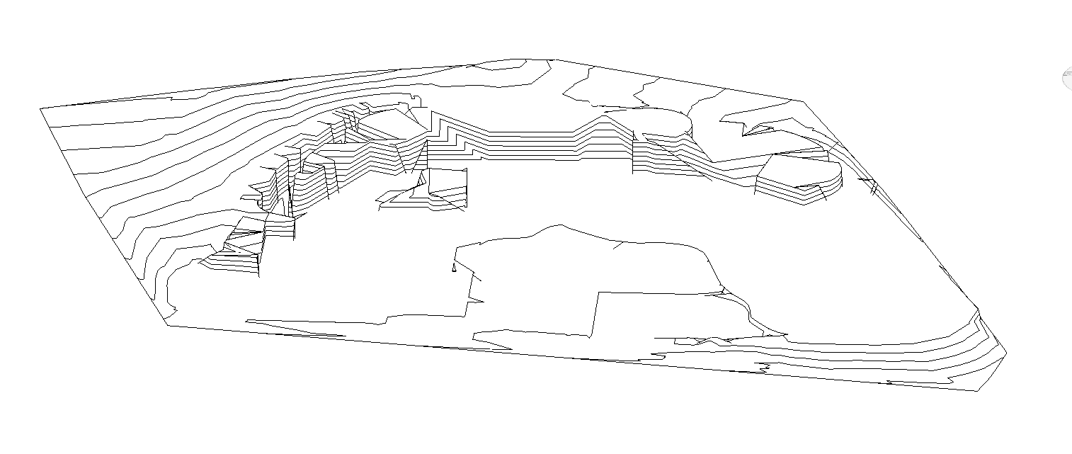
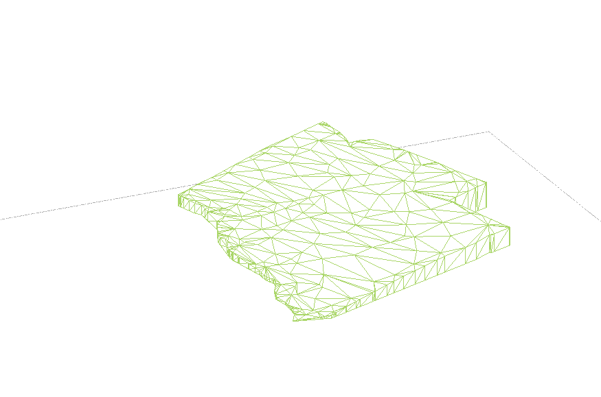
Hi guys, Effectively, the site model export to revit is a headache... I understand that this relies more on Revit then in in Vectorworks, but you should really look to this. It is a nightmare for everybody... I see that Autodesk uses a procedure to transmit Civil3d toposurface to Revit (using DWG file), I'll try to go through the export settings in Civil 3d to see what is "good enough" for Revit, because, from my understanding, I'm bringing "too many points" to Revit and the triangulation just goes crazy.... Putting the original site modifier and then start putting points based in our site modifiers?!? Anybody tried something like this before? Original Site: With Contours (DWG): With Mesh (DWG): IFC (doesn't even enter as a valid input for terrain):


-
Drip area - Trouble with direction of the drip line
jpccrodrigues replied to carlotta curti's topic in Site Design
The secundary pipe connects the drip line, not the other away around. Design the drip lines and the connect them with the secundary pipe. -
Hi, good morning Eric, Exporting directly a site model from vectorworks to revit didn't work. The model enters as a "generic model" in revit and it doesn't work as an input for the terrain creation. Craziest thing: you export that same element in DWG and re-import it into revit and then it "reads" to become a terrain. But the mesh / TIN surface isn't really a good base for terrain creation in revit, all the reasoning behind it soles in direct point manipulation. From what I've been reading, two main inputs are admissible: DWG with contours or points or a CSV file. The export RVT from VW always enters in revit as a generic model, it doesn't transform into a native revit object. So, I always need to make that bypass through autocad (or export dwg from vw and just ignore the rvt export). With that said, now we enter in the trial and error stage, where we have to test and see what procedure gets the best results. I think the contours will be the solution, but tomorrow I'll post the results. For the future, it would be very important to get a direct relation between vw site model and revit terrain. Earthworks is the base of our work and if we aren't able to communicate it, then we have a problem. I know that VW works to get that connection done, site model is a fantastic tool comparing to all other bim softwares available, but... Revit is the standard in the industry and if we want to "sell" ourselfs as a BIM software, we should assure that we have procedures, guidelines or software developments to allow that exchange of information. Another two points to think: geolocation vs design close to the user origin. When we use geolocation, it allows a lot of tools but then, being very distant from the internal origin, some errors start appearing. And the site model export into ifc file. It requires a lot of tricks to get it done. Sorry for the long text, hopefully it can transmit some of our experience using the software and communicating with other offices.
-
Hi, need some help... Trying to put a site model into revit, but the terrain object within revit is a headache... Does anyone know if we can export a site model into a CSV file? Making a worksheet of points? Did anybody faced this question? Last resort I explode the site model in 3d view, take out the 3D contours, export as DWG and use them to create the terrain. But, if I'm able to, at least, extract a point cloud from the file, the end result would be better... Thanks
-
Drip area - Trouble with direction of the drip line
jpccrodrigues replied to carlotta curti's topic in Site Design
Draw the drip line individually, not a drip area. You can offset the arc, select them, create object from shape, drip line outlet and then connect them with secundary pipe. -
Hi guys, Can anyone tell if the export ifc works with site model? I'm working with an office that uses revit and the site model object is becoming a problem. Export directly a RVT file, the site model becomes a generic volume, that hardly "translates" to a terrain object within revit. The export ifc isn't working, tried a lot of variations on its settings, but the file comes empty. Anyone can give a help? Thanks!!
-
Quick question: is there any way or procedure to export a vectorworks site model and be able to transform it into a revit terrain?
-
Ohhh the wait... 😄
-
How do we edit the new Path Modifier?
jpccrodrigues replied to hollister design Studio's topic in Site Design
Some error in the process, bug... The doubt is always in the back of our head... The last error that we found was that the site modifiers done with the sp1 maintain the errors, but creating the same site modifiers with the Sp2, no errors. To figure this out: 2 days... Seems like vectorworks launched the new workflow for the site model in a beta version and now is correcting the errors as they keep appearing. In the same year that perpetual licenses will be discontinued, having to live with a version with bugs, errors and erratic behaviors only creates doubts on our team. Seriously vectorworks, get this workflow cleared and launch some good webinars so we can get back on track with the site model tool. Until then, 2022 and a lot of doubts. -
Site Modifier Transversal Profile V.2023
jpccrodrigues replied to jpccrodrigues's topic in Site Design
Hi, good morning, @Zsombor thanks for your help. We did our test and worked as well. And the solution creates another problem... putting the drawing close to the origin (the point that solved the problem), we loose the georeferenced features. Either we have site model or georeferenced features... Another point to sign: in medium-complex site models, cut and fill calculations are impossible. 6 hours and nothing. Vectorworks should really look at the stability of the new site model workflow and present webinars ASAP so we can assess if we are facing bugs (and you can identify a lot of them corrected in the last SP2) or if it is only adaptation to a new way to work.