Matt Panzer
-
Posts
3,338 -
Joined
-
Last visited
Content Type
Profiles
Forums
Events
Articles
Marionette
Store
Everything posted by Matt Panzer
-
Hi Jeremiah, Do you have any idea what might be triggering the problem? Are you using Project Sharing, Design Layer Referencing, and/or Design Layer Reference Viewports?
-

Where to add/edit VW built-in sheet sizes?
Matt Panzer replied to Gilbert Osmond's topic in General Discussion
I think creating custom page sizes through the page setup (as Nikolay suggests) is the only place you need to add them. You can then use "Fit to Page" in the sheet border to have it always match the sheet layer's page size. -
Hi Nick, Have you sent the file to tech support? While it may not be a file problem, that file seems to expose the issue.
-
@tismacfan2, @Andy Broomell Yes. This is a known bug and should be fixed for an upcoming service pack. Can you both send me files the show the problem you're having. While it should be fixed, I'd like to make sure you're specific problems will be addressed.
-
Thanks for the file, Sam. Do you know if this product is available in any other file formats to download? I tried importing this and the geometry comes in a bit distorted and has a lot over unnecessary complex geometry. I would try other CAD file formats before trying to use this. Assuming you're using Vectorworks 2019: Generally, what I would do is create a symbol of the object. The Revit import did come in as a symbol, so that step is taken care of. Assuming only 3D geometry imported (as in this case), I would then edit the 3D component and clean up anything I can. With mesh geometry like this file, this is not an easy task. Once I have the 3D cleaned up, I'd edit the Top 2D component, right-click in the background and choose the "Generate 2D from 3D Component" context menu command. If you have good clean 3D geometry, this command should generate a good 2D graphics that you can further edit to suit you needs. If you have meshes, the results may not be so great. In the case of the attached Revit file, Vectorworks could not manage to create any 2D graphics from it. Judging from the 3D mesh, I'm not surprised. If you can find a better file format to import, give the steps above a try.
-
Hi Sam, Can you post the Revit file you're using?
-
After setting the document units to fractional display, select the dimensions and notice the "Prec" setting in the Object Info palette is blank. Set it to something reasonable and it should work. You might ask why this happened in the first place? Well, It looks like the dimensions were placed using decimal display with the display "Prec" set to the maximum. After changing the document units, it appears that Vectorworks is not assigning it an appropriate fractional value and it remains blank. When this happens, it displays in that format. From what I see, when using decimal document units, keeping the display precision at ".000001" or lower will prevent this from happening. I will report this bug.
-
Section Viewports w/ OpenGL Background Render
Matt Panzer replied to Andy Broomell's question in Troubleshooting
Hi Andy, Thanks for the file. I definitely see the issue! The issue may've already been addressed for an upcoming service pack but I submitted a bug with your file just to make sure. -
to renew or not to renew (that is the question)
Matt Panzer replied to Phil hunt's topic in General Discussion
900 DPI seems a bit high. Have you experimented printing out lower resolutions to see if there's a noticeable difference? Also, I would recommend experimenting with render settings using Custom Renderworks. You should be able to get away with lowering certain settings with no noticeable loss in quality but have a noticeable difference in render speed. -
I setup Custom Page sizes with no margins for each size needed. I then set Page Setup to "Any Printer" and choose the custom size I want. I do this so my exported PDF files are created with pages without margins being trimmed off. Mind you, I don't typically print projects directly from Vectorworks. I publish to PDF and print from that if needed. I do this to ensure what I print matches what I send to the client or printing service (PDF).
-
Section Viewports w/ OpenGL Background Render
Matt Panzer replied to Andy Broomell's question in Troubleshooting
Hi Andy, I have not seen this issue. Can you attach a small file that has the problem? -
VW 2019-The symbol does not react on class selection
Matt Panzer replied to oien's question in Troubleshooting
The Add Profile option adds a profile around only structural objects (walls, stairs, slabs, roofs, etc). You can also select the "Merge with Structural Objects in Sections" in the Object Info palette of 3D objects and they will also get the profile line. -
VW 2019-The symbol does not react on class selection
Matt Panzer replied to oien's question in Troubleshooting
I just submitted a bug on this. We fixed a bug related to this, but the problem still happens when not using the "Use Attributes of Original Objects" option in the Advanced Properties. Thank you for brining this to our attention! -Matt -
Hi @Sky, You're right. I still see the issue in 2019. I added a note on the bug report to try to bump this up in the priority list.
-
Hi @Mik , There is a bug filed on crashing related to rendering in Hidden Line with slabs and roofs. We saw this crash in several user logs (including mine) and have been trying to create reproducible cases to make sure we get to the source of the problem. The crash in my user log was related to the slab object and I was never able to reproduce it. However, I can easily reproduce it with a roof and added the steps to the report last week. If you (or anyone) come across a reproducible case using a slab, please let me know.
-
Section Viewport with turns / interior unwrapped elevation?
Matt Panzer replied to MattG's topic in General Discussion
You could create interior elevation viewports, edit the underlying section lines of the interior elevation marker to the desired positions, then move the viewports next to each other. -
Camera Match Rendering showing black outline
Matt Panzer replied to HEengineering's question in Troubleshooting
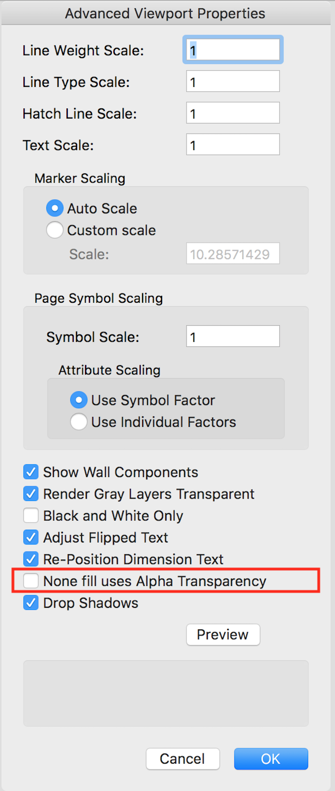
Hi Matt, Thanks for the file. I found the culprit. Select the viewport, edit its Advanced Properties (via the Object Info palette), and deselect "None Fill Uses Alpha Transparency". Update the viewport and the problem should be gone.
-
Camera Match Rendering showing black outline
Matt Panzer replied to HEengineering's question in Troubleshooting
Do you have a simple file showing the issue? What's the exact version of Vectorworks you're using (2017 SPX build XXXXXX)? -
We are aware of this issue and it's a high priority bug. One way around the issue is to set the viewport's Detail Level to "Low".
-
Screen Plane In Symbol 3D Component
Matt Panzer replied to BenV's question in Wishlist - Feature and Content Requests
While this behavior is not a bug, the edit modes of symbol (and plug-in) components is an area we're working to improve. @Jim Wilson, can this thread be moved to the Wishlist forum? -
Issues Publishing/Exporting Cropped Camera Match Sheet
Matt Panzer replied to Steve Clarkson's topic in General Discussion
Hi Steve, Select the Camera Match object and select the "Clip Photo to Viewport Crop" option in the Object Info palette. NOTE: When rendering the viewport in OpenGL or Renderworks modes, the "Show Photo" option (in the Object Info palette) should be off because those render modes use a Render Background of the photo. Render Backgrounds will only show within the crop. -
Plug-in object (door) rendering...
Matt Panzer replied to MRD Mark Ridgewell's topic in General Discussion
Hi Mark, I noticed all the classes in the dialog are "by instance". Try editing the style and set all of them (that you want all instances to use) to "by style". This should do the trick. -
The best solution for this would be a custom plug-in or a marionette object. The object could contain two instances of a directional light symbol and have separate rotation angle parameters for each. It should be fairly easy to create for someone experienced in creating these objects. You might find some help with this in the Vectorscript, Python, or Marionette forums.
-
Hi Will, I received the message but do not see a file.
-
@Will, Could you send the file to me privately? I can recreate the problem, but sometimes real user files better demonstrate the issue.