All Activity
- Past hour
-
Is it possible just subtract a number of a variable on the data tag field? I want to make this: Or in fact, I want the Total Weight of all Instruments on a truss without the truss weight. If it can be dynamic will be perfect!

- Today
-
Hi all, Just wondering if anyone knows how to fix this. When I am inside of a group in a large file then there is significant lag. The lag makes it difficult to scroll and zoom etc. The lag only exists if I have "show other object in editing modes" turned on. It seems to be on Windows and not on Mac. Does anyone know how to fix this? I have a new high spec laptop with latest drivers etc. It doesn't seem to matter which Vectorworks year I'm using, even legacy versions have this issue. Thanks
-
Positive Prompt: Image of a single isolated red rose bush on a solid white background. Photorealistic image. flat solid color background Negative Prompt: background lighting Creativity:49

-
A positive prompt of "Over a plain white background" should get your something relatively easy to crop the background from.
-

AI Visualizations-Thougthful discussions
Matt Overton replied to Luis M Ruiz's topic in AI Visualizer
Surely, any thoughtful discussion of AI now must include recent events of ChatGPT literally stealing someone's voice. I'd think they bet the farm and have lost with the hubris of such a move. -
Is there a standard prompt that will isolate the "subject" from the background like an image that would be then useful for image props? Negative prompt - Background also variations of the positive prompt "remove background" have no effect.
-
Worksheet for planting for visible viewport on sheetlayer only.
Pat Stanford replied to Tien's question in Troubleshooting
Then you probably don't want the Layer criteria. My guess (and I have not tried to mock this up) is that it is looking for object on the Sheet Layer that are also inside LOWERGROUND1. There may be object in the viewport that match the criteria, but those object are not on the Sheet Layer. -

Worksheet for planting for visible viewport on sheetlayer only.
Tien replied to Tien's question in Troubleshooting
Good questions Pat, PP_LG_1 is a sheet layer. LOWERGROUND1 is also on the sheet layer. My assumption is the criteria will see the viewport and work its contents out from there. So the schedule and viewport are all on sheet layer. But maybe this is not the way to do it? -
Just an idea: How about using VP Styles for this ? Any custom settings of the scale can then be recalled with the style ? HTH.
- Yesterday
-

Redshift Render - cannot get lit fog to work
Anthony Neary replied to Anthony Neary's topic in Rendering
Putting an answer here for anyone else running in to the same "issue." Redshift needs a higher fog density than RW renders, so all I needed to do was increase the fog density. What also helped was setting spotlight instrument light settings to realistic falloff. -
 LanternSh4rk joined the community
 -
@klinzey Totally get it... we have symbols and cross sections of truss that don't exist in VW yet. We are programming and sharing across the nation. I created a cross section to function with the symbols until they are created.
-
Nice model! FWIW, these would be easily achievable with roof faces. If you're trying to get roof faces with different pitches to match, you could use the connect/combine tool to get the hip angle (in plan), then you'd use that to make up the roof structure. In regards to your initial question with solids modelling, I have also noticed solids going awry after many operations, as I'm guessing theres some sort of limitation to recording the number of operations for solids modelling (add, subtract, intersect, etc). I'll have a crack at your roof structure above when I get some free time, to see if I can replicate that model with roof faces.
-
Redshift Render - cannot get lit fog to work
Anthony Neary replied to Anthony Neary's topic in Rendering
DM'd you. Thank you very much Dave. -

Redshift Render - cannot get lit fog to work
Dave Donley replied to Anthony Neary's topic in Rendering
@Anthony Neary Can you send me a small copy of your file that shows the problem? -
Apologies for the double post. I had posted this in entertainment but I should have posted it here instead. Hi all, for the life of me I can't figure out why lit fog is not working for me. - Background has lit fog engaged at 20% with smooth consistency - Background is assigned to the Render Style set for Redshift type - indirect lighting set as exterior 1 bounce for faster test renders - Lighting is set as Ambient Lighting 5% - Ambient occlusion on at 50% strength at 4' - shadows are engaged - textures are engaged - colors are engaged - denoise and camera effects not turned on - all of my lights right now are Spotlight objects - via the Edit Light menu - lights are all set to cast shadows, lights all set for soft shadows, lights all set for lit fog, not using emitter but just using the regular brightness, falloff set to smooth I can see the beams in the fog in OpenGL but they won't render in Redshift. I am at a total loss, but I must be doing something wrong somewhere. Thoughts? Thanks all.
-
Hi all, for the life of me I can't figure out why lit fog is not working for me. - Background has lit fog engaged at 20% with smooth consistency - Background is assigned to the Render Style set for Redshift type - indirect lighting set as exterior 1 bounce for faster test renders - Lighting is set as Ambient Lighting 5% - Ambient occlusion on at 50% strength at 4' - shadows are engaged - textures are engaged - colors are engaged - denoise and camera effects not turned on - all of my lights right now are Spotlight objects - via the Edit Light menu - lights are all set to cast shadows, lights all set for soft shadows, lights all set for lit fog, not using emitter but just using the regular brightness, falloff set to smooth I can see the beams in the fog in OpenGL but they won't render in Redshift. I am at a total loss, but I must be doing something wrong somewhere. Thoughts? Thanks all.
-

Tree Root ball not accepting the Viewport class setting
Gepland replied to SthavyaK's topic in Site Design
As Poot already hinted, the class option "use at creation" is not checked when creating a class from within the plant style dialogue. Look for the specific class in the navigation settings, and check the box. 🙂 -
@MGuilfoile I coined a saying for MiniCAD a few years ago, How you render is how you draw. People I assist with VW often draw then attempt to map textures and find they hit snags ... see attached Left item at the start is Perimeter Mapping - Right item is a combined Plan / Cylinder mapping adjusted for the most part with the Attribute Mapping Tool - The geometry was adjusted (up front...) to match the Image Shader in the texture so the fit was logical / easier Peter Mapping Perimeter vs Plane.mov
-
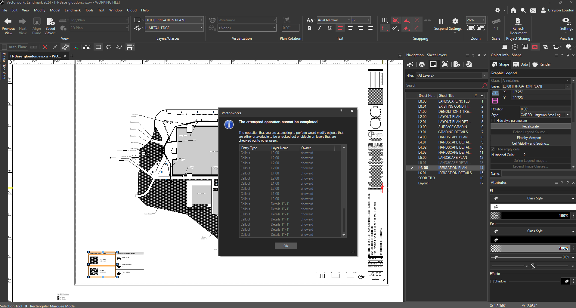
 Hey all, My collegues and I have been using VW project sharing for a couple of projects now. We are using VW 2024 (update 5) landmark edition. We have noticed some seemingly random check-outs being required to update some viewports, graphic legends, or worksheets. I've posted an image below that shows me trying to recalculate a graphic legend (highlighted in the lower left hand corner) and a prompt from VW to check out callouts on totally different design layers and sheet layers that have nothing to do with the graphic legend I'm trying to update. This has happened with other instances but this is the latest one that has prompted me to ask about it. Any help is appreciated. Thanks.
-
@Claes Lundstrom Curious ? - What are we looking at in the Gunner - NHL - Yamaha Image qbove ? Peter
-
Are the 3d plants from the VW Libraries?? Or did you import them into VW? Also., you were a bit vague regarding your render settings, etc ?? The Render settings can have a LOT to do with how long it takes to render. I assume you are rendering to a sheet layer viewport?? IF you are just rendering on a design layer it will t take wayyyy longer to render as opposed to rendering a viewport on a sheet layer. 150 megs is not really that large a file.
-
 Scott Evans joined the community
 -
The highest scale in VW viewport dropdown is 3" = 1'-0". I have a detail that needs to show in the drawing label with 6" = 1'-0" text. That scale is not needed very often but not unusual at all. Currently it is set to "1:2" scale which is correct and works for sheet vp but shows the scale default language as "Half Actual Size". My contractors won't understand that and it will get screwed up in the field. We understand numbers better than words. Call me fussy, but my goal is to have dwgs that don't require any thinking. Any suggestions? I've been adding text separately in the vp annotation above the "Half Size" scale that redundantly says 6" = 1'-0", but it looks awkward and probably kluge-prone.
-
Custom Speakers & Yokes
C. Andrew Dunning replied to jameslye's question in Wishlist - Feature and Content Requests
As of the September release, the Landru Design version of the audio tools includes this feature. -
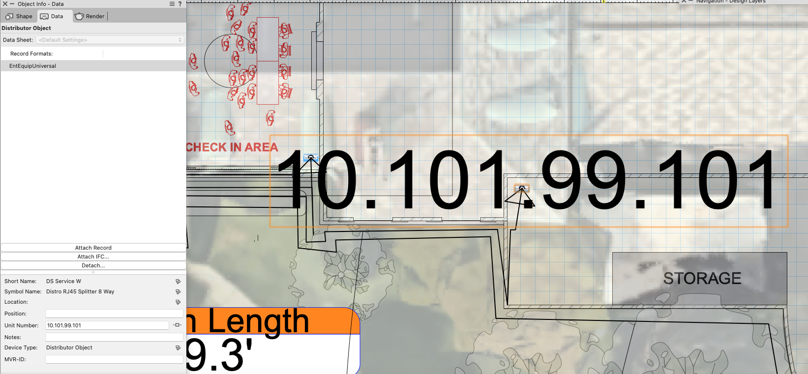
I have a handful of distributor objects for data nodes (switches, gateways, etc) that were edited from the default "distro RJ45 splitter 8 way" object. I'm using the ID field to record the nodes' IP address. When there is content entered in that ID field, it automatically appears as text over the symbol. I can not understand where or how to edit this characteristic in the editor. Can anyone point me in the right direction? I'd prefer to not have it display AT ALL, and I will add a label as I see fit on my own (which I can then hide without hiding the node itself). Thanks.

-
So I have a VWs file with a fixture having 4 products - P1, P2, P3 and P4. What I am looking for is to upload an excel file (use the concept of excel referencing) and that should check if the same product exists in the drawing or not. Example - Let's say P1 got replaced with P5 and P2 with P6 Excel looks like following Fixture name | P5|P6|P3|P4 Now when I upload excel in VWs then that should change the fixture drawing to have 4 products - P5, P6, P3 and P4. This is what I am trying to achieve (swap symbols in a drawing through excel).