Cristiano Alves
-
Posts
209 -
Joined
-
Last visited
1 Follower
-

Worksheet on Drawing is a blank square
Cristiano Alves replied to A.D.K.'s question in Troubleshooting
Probably I made it and now I just can see a square like you without any data. I deleted and added the worksheet to the drawing again, but I just can see an empty rectangle. 😕 this is a bug?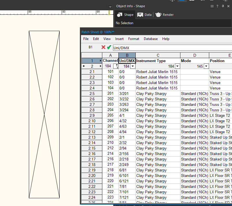
-
Extensive Patch List: Creating a Two-Page Worksheet Table
Cristiano Alves replied to Cristiano Alves's topic in Entertainment
Thank you a lot for your help Just in case you try find a better solution for it: This approach sounds good, but can we "count by line"? Because I don't have a sequential number of the fixtures: For example, In this project I have 201 thru 222 for beams, 301 thru 28 for spots With this workflow, we need to change the criteria for all projects. It would be good if we could define by line and we can copy the worksheet from one project to another project, and this way works all the time. -
Conditional Formatting within worksheets
Cristiano Alves replied to Mike T's topic in General Discussion
Resurrecting this again 😞 -
Hello Guys I've encountered an extremely large patch list that, when inserted into a Sheet Layer, becomes unreadable because the text is too small. How can I create a worksheet table that spans two pages?
-
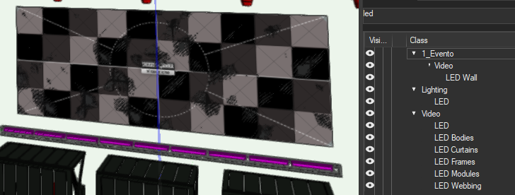
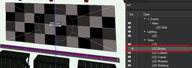
Good morning Justin I had already reported this problem. It's clearly a Z-Fighting problem and you can read it here in the post: If we export the models from Vectorworks and import them into another software, the same thing happens. This is a problem created by the Front Tale and the LED Bodies, if we hide the "Bodies" class, this problem will no longer happen.
-
I understood. You're right. But now, as a member of the Vectorworks team, I leave here the question: The problem with angles is not the only one when I have to resort to this method to do paperwork for vertical structures. In this case, as I already mentioned, there are 6 structures with 2 leaders each, I cannot group them because this method stops working; The only way is to use Shaded mode but this makes the documents extremely heavy, and the reading is not CAD. This type of staging is not new, is this the only option? Is there something in your Vectorworks development pipeline that will facilitate this need that many must-have? (I even find it strange how there aren't more people reporting or asking about this, could it be that I haven't found the correct method to do this?)
-
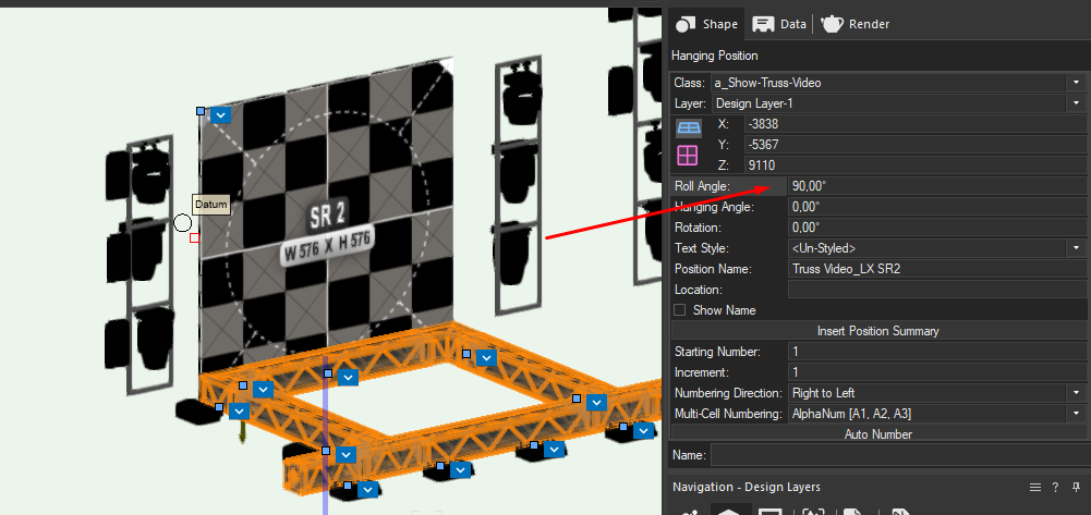
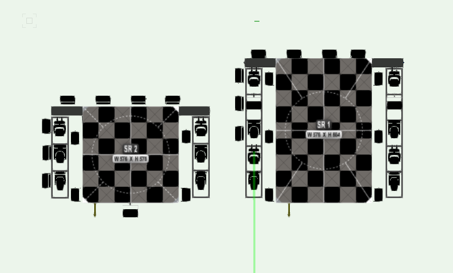
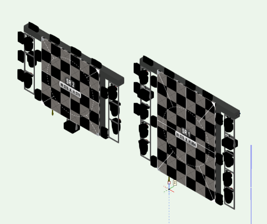
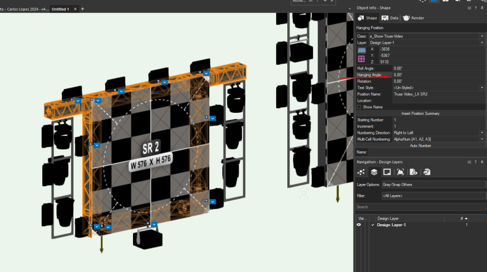
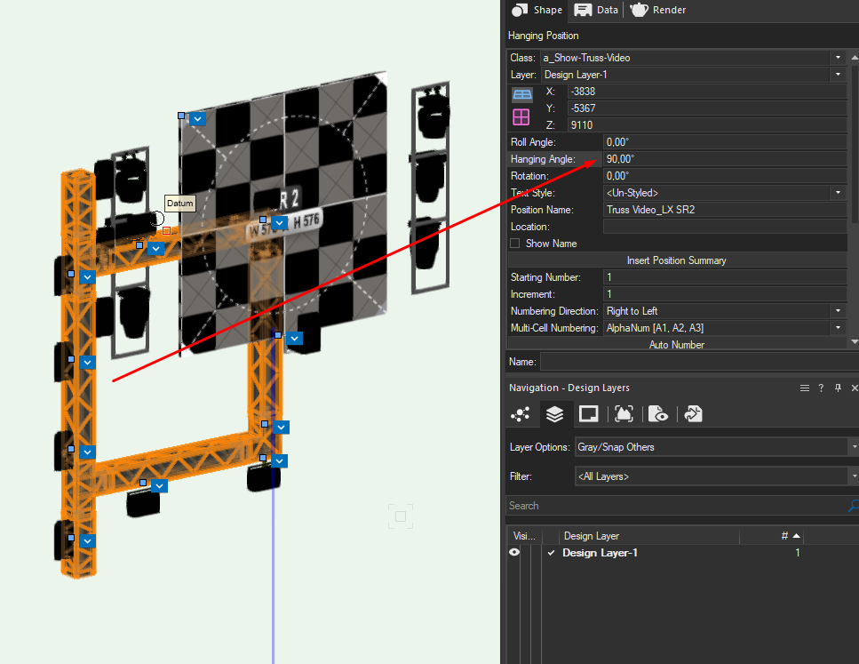
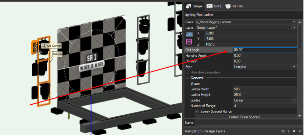
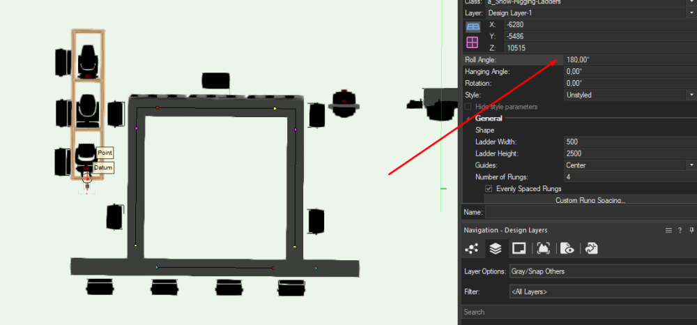
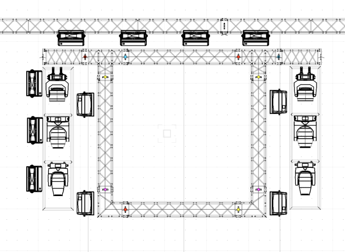
Hello @markdd I am coming back here because I think this is the best shot to produce the correct paperwork for my last project. However, I tried your method and the results are different. This is part of my project: (FRONT VIEW) (RIGHT ISOMETRIC VIEW) For my example, I will use the truss off Screen SR2. As you said on your video, If I change the Hanging Angle I get this: Not the same result. If I use the Roll Angle I can get this: The screen doesn't move with the hanging position: And the Ladders also don't move. Strange results, and I have 6 Hanging positions like these (with 2 ladders each). The method that you said is the best way to apply in this case too? Project file in attachments. DG-CL24-VWForumPaperworks Front View.vwx

-
Construi uma Data-Tag para Poder associar a LED Screens. Consigo encontrar encontrar as variaveis todas para construir a Data Tag: Comprimento e a Largura (e com isto calculo a àrea), o peso do ecrã, e o número de pixeis. Contudo não consigo depois associar a arrow ao LED Screen. Tambem não encontro o "nome do LED Screen". Alguem sabe como consigo agarrar a Data Tag a um objecto LED Screen?
-
Good afternoon, I'm doing some plots and as there are still no easy tools to make viewports in 2D/Plan I would like to understand how I can activate the colors of Data Visualization in a front view for the stage Could you help me, thank you very much in advance. Regards Cristiano Alves
-
Data Viz in the Equipment Summary Key
Cristiano Alves replied to Scott C. Parker's topic in Entertainment
THANK YOU SO MUCH 😄 -
I figured out the problem with LED Screens. The problem was the LED Bodies and the LED Modules in Z-fighting (same plane). I imported my stage made in Vectorworks into another software and the same problem with the stains happened too. So in debate with other users , I realized that if I moved the frontal plane 1mm away from the cabins (modules) the problem would stop happening. So in Vectorworks, I went to the LED Screen classes, and tried the various options. Since it is not possible to add a 1mm offset of the frontal plane, I hid the LED bodies and the Z-fighting effect stopped occurring, which means that the problem is really the frontal plane will be coplanar with the frontal plane. How can we solve this?

-
WOW It really is a very good tool. THANK YOU How is it possible to use vectorworks VGX models? Because I exported in VGX but the cube was not applied and so I cannot see inside the building.
-
Truss inventory report - use hanging position data?
Cristiano Alves replied to livespace josha's topic in Entertainment
Up After watch some tutorials about Spreedshets and reports I still couldn't do this. -
SOLVED, The Universe, and magically Universe/Adress are correct 😅
-
Can you specify it better? 😄 I had the same opinion until I saw what a friend of mine did on Fusion 360 with the trackpad. I started to get used to it and you can actually do a lot of things. In this case of Vectorworks, I just wanted to be able to "travel through the project better". I'm often at the location/venue with the client and laptop in hand. We're standing and we don't have a table, so I can have a mouse in my hand. 😞