All Activity
- Past hour
-
From Help: It works with any planar 3D Poly for me...
-
@Benson Shaw Just stumbled over this, and was very suprised that this should work. Making a few tests I'm shure this works only with a 3D triangale made from a 3d polygon, since a triangle spans a plane in 3d space...
- Today
-
Hello, You should also check out @michaelk excellent Theatre Row plug in: https://www.verysmallgroup.com/vectorworks-plugins Cheers, Peter
-
Hi Alan, To answer your question the reason is because it is a 3D only symbol. If you cut the objects from the 3D component and paste into the 2D then the document preference of 'Adjust Flipped Test' can then work. Otherwise the objects are just planar objects in 3D. Troy is correct in that you should look at the ANZ Electrical Services tool. Right click on the page and go to the ANZ Video Tutorials to see the two about it's use. Cheers, Peter
-
Hello, What macOS are you on? Go to 'About this Mac' to find it. Then make sure you are on a supported operating system. Click here to check. Cheers, Peter
-

Crop edit not showing objects beyond crop line
Peter Neufeld. replied to MGuilfoile's question in Troubleshooting
Hello, My guess is that you have an out of date graphics driver. You are probably best to contact your local technical support so they can have a look at your DxDiag file. Cheers, Peter -

Auto Hybrid objects disappearing
James Dawson Design replied to James Dawson Design's topic in Site Design
OK, the cut plane elevation value was the issue. All AH had a 1000 vale, however the disappearing AH objects had a Z value higher than that. i.e. 2400. I changed the cut plane elevation value to 3000 and they now dont disappear. Time to learn a little more about this behaviour. -
 Gelec joined the community
 -
 Dear McCartney Design Team, I am very interested in the position you have available for a fast and accurate drafter. With 6 years of experience in interior design(3 years of retail design), I have been involved in all stages from initial planning to final implementation. During this time, I have developed a wide range of design skills and experience, enabling me to independently produce comprehensive drawing sets including plans, reflected ceiling plans, internal elevations, and shopfront drawings. I am enthusiastic about the opportunity to collaborate with your team. I believe that my skills and experience would add value to your projects, and I am eager to contribute my talents to your team. I look forward to discussing this opportunity further and hope to have the chance to work with the McCartney Design team. Thank you for considering my application.
 -
Another option is to turn the geometry into a hybrid symbol. This can be very quick using the 'Generate 2D from 3D Component' command.
-
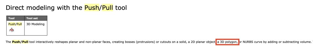
Late reply, hope this is solved already. Here are some comments and a workaround. 1. Model>Extrude needs 2d source object(s). The selected 3d Poly will therefore not extrude and will instead generate that error message. 2. Push/Pull 1st mode should work with the 3d poly. Don't know why it fails. Maybe something wrong with the poly, the working plane, or ??? 3. Workaround: Put drawing in Top/Plan. and set the working plane to Layer. Select the 3d Poly, Modify>Convert>Polygon - result is a 2d polygon (or a group of 2d polygons - Compose them and ungroup), Model>Extrude to desired height of building, (or flyover view and use Push/Pull) Set Bottom z to 351.2 or as desired. Repeat for other shapes as necessary. HTH -B
-
Auto Hybrid objects disappearing
James Dawson Design replied to James Dawson Design's topic in Site Design
guess I will have to learn what cut planes are. You may well be correct.I -
 HCP joined the community
 -
Nope. I imagine the plug-in command would create the dialog with a pop up menu. I imagine you could tab to the pop up, but I'm not sure the arrow keys will travel the choices, but maybe. So, 1. select a hoist 2. initiate the command which shows the dialog with a pop up. (the dialog has to create the list of lengths 3. tab to the pop up 4. arrow key to the length 5. hit return 6. the command code writes the choice value into the field of the custom record. I think it would be easier to code just a query for the length that is then written to the record. compared to making the dialog and processing it, the ease in coding would more than make up for the typing of the length HoistHandle := FSActLayer; {assumes the hoist in on the active layer} LengthStr := StrDialog('Input cable length', ''); SetRField(HoistHandle, recordName, fieldName, LengthStr)
- Yesterday
-
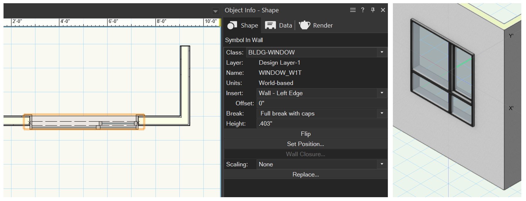
As Tom tried to explain above, if you custom model the window you still want to use the Window Plugin Object, but check the Use Symbol Geometry check box and then choose your custom symbol. BUT, what you really want to do is spend the hour or two learning about the Window Plugin Object and what it can do so that you don't have to model every window from scratch. Unless you are doing something really custom, at least 80-99% of the windows you will be using can be modeled using the Window object.
-
I created my own 2D/3D symbol from scratch. But it doesn't have all the Window settings available similar to the last VW file I posted. In the new one, I can add or edit a tag, but I'm unable to show the tag I've added. Is there a way to make this symbol a "window" symbol and behave like the ones found in the resource library/VW libraries/window styles/standard windows? Wall_Window_new.vwx

-
I modelled my own...
-
Thank you @Tom W. Yes, got there in the end. Seems a bit awkward but now I know, it will be quicker next time. On a side note, do you know if there are EV Charging Points in Vectorworks? I can not seem to find any in the Resource Manager. Kind regards Mike
-
Your Window is 'non-standard' in that it uses symbol geometry, i.e. rather than opting to have the geometry generated by the PIO you have decided to use your own custom geometry. You have basically decided to forego the Window Tool + created your own window symbol from scratch but rather than inserting it in the Wall directly you have used a Window as a container: doing it this way means that your symbol becomes a 'Window' in as much as it can be tagged + scheduled along with other 'normal' Windows. To get your head around it better I would start again in a new blank file + try creating your window from scratch using the Window tool. If you can achieve what you need using the tool on its own you don't need to go down the 'Use symbol geometry' route at all. Normally you'd only resort to using a custom symbol if you are unable to create the configuration you want using the tool alone + even then, you don't need to incorporate the symbol into a Window unless you expressly need it to be a Window: you can insert it straight into the Wall as it is. Basically what you are doing is relatively advanced + complex + I imagine most people happily use the Window Tool without ever utilising the 'Use symbol geometry' option at all or at least fairly rarely.
-
Activate record field by keyboard shortcut
Pat Stanford replied to Wood's topic in General Discussion
@Sam Jones Do you have something like this in Autopilot? -
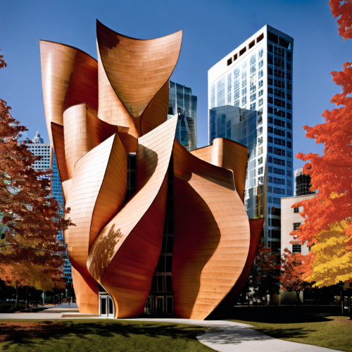
Here's another one overheard by the therapist... Prompt: Jealous stalker is probably the best description of my relationship with Frank Gehry. How does he come up with those crazy buildings? There must be something in the maple syrup. I'm sure I'll have offended a few here with my silly AI prompts, but I think it pretty clearly illustrates how badly it rips off artists and creatives. In these examples, it basically took "Frank Gehry", "Maple", and "buildings" as inputs. The last image simply uses those 3 items alone as the prompt.


-
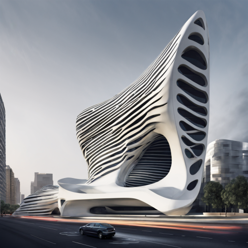
Who should be worried... Architects or their therapists? Prompt: I'm a lazy architect questioning my life choices. I probably should have become an accountant. Make my boring buildings look cool and futuristic like Zaha Hadid so I can get back to counting my money.

-
Hi @Tom W., I'm not understanding the relationship between the two: Plug-in-Object (PIO) and the hybrid symbol. I assumed that they are one in the same. Can you please elaborate further? Apologies, I come from a SolidWorks background and I'm trying to adjust my learning towards how VW approaches 3D modelling/editing.
-
Pat- Thanks for being my personal tech support here 🙂 The goal is to click a hoist, type the keyboard shortcut, have a dialog pop up that I can manipulate with the arrow keys to select the specified motor cable length, and then store that selection to a custom record that I have previously attached to the hoist. Main goal here is eliminating the mouse travel to the oip and additional mouse clicks. They really add up on large shows so even tiny efficiencies are huge. Thanks again!
-
It could be very useful to be able to open Vectorworks on an iPad. Will that be possible?
-
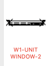
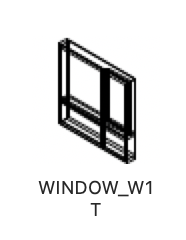
The is the Window Style that you are editing: This is the hybrid symbol that I was referring to in my posts: The Window PIO is getting its geometry from the 'WINDOW_W1T' symbol rather than the PIO generating the geometry.
-

Export Files via Vectorworks Cloud Service
inikolova replied to maxstk's question in Wishlist - Feature and Content Requests
Cloud Revit Export is scheduled for release with Vectorworks 2025.