Greg Rosenke
-
Posts
7 -
Joined
-
Last visited
-
Hello, I'm new to Vectorworks and data tags. I need to update my sheet layers so the unit text on each floor plans are designated as LH or RH, depending on which side of the hallway they're on. The floor numbers (cyan) are static values The unit numbers (blue) are sequential and are driven by the "Edit Tag Data...", as 01, 02, 03, 04, etc.... How would I create the data tag layout string values (yellow) and be able to switch between LH or RH?

-

Dimension class visibility not toggling to show off
Greg Rosenke replied to Greg Rosenke's topic in General Discussion
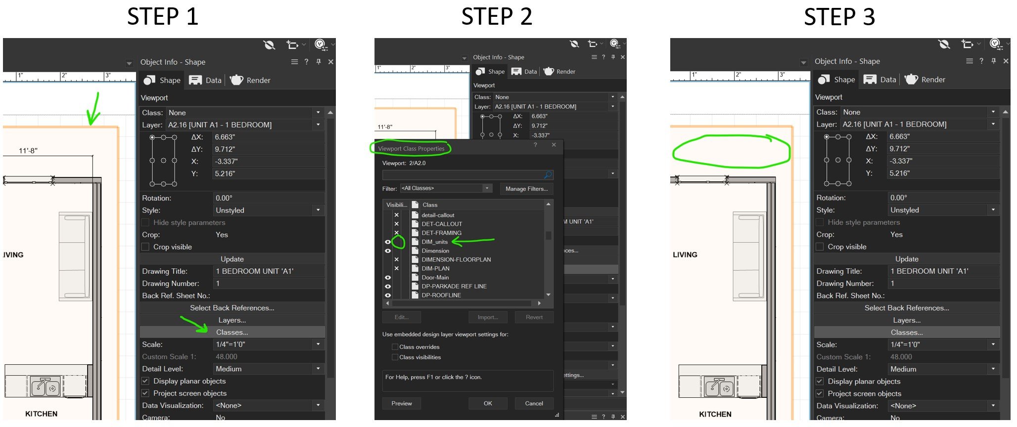
@Jeff Prince ..."not your the navigation panel" was the kicker. Ah, that makes more sense. Selecting "Classes..." in the Viewport was the missing puzzle piece. I'm a visual learner. Thanks all. See pics: .
-
Dimension class visibility not toggling to show off
Greg Rosenke replied to Greg Rosenke's topic in General Discussion
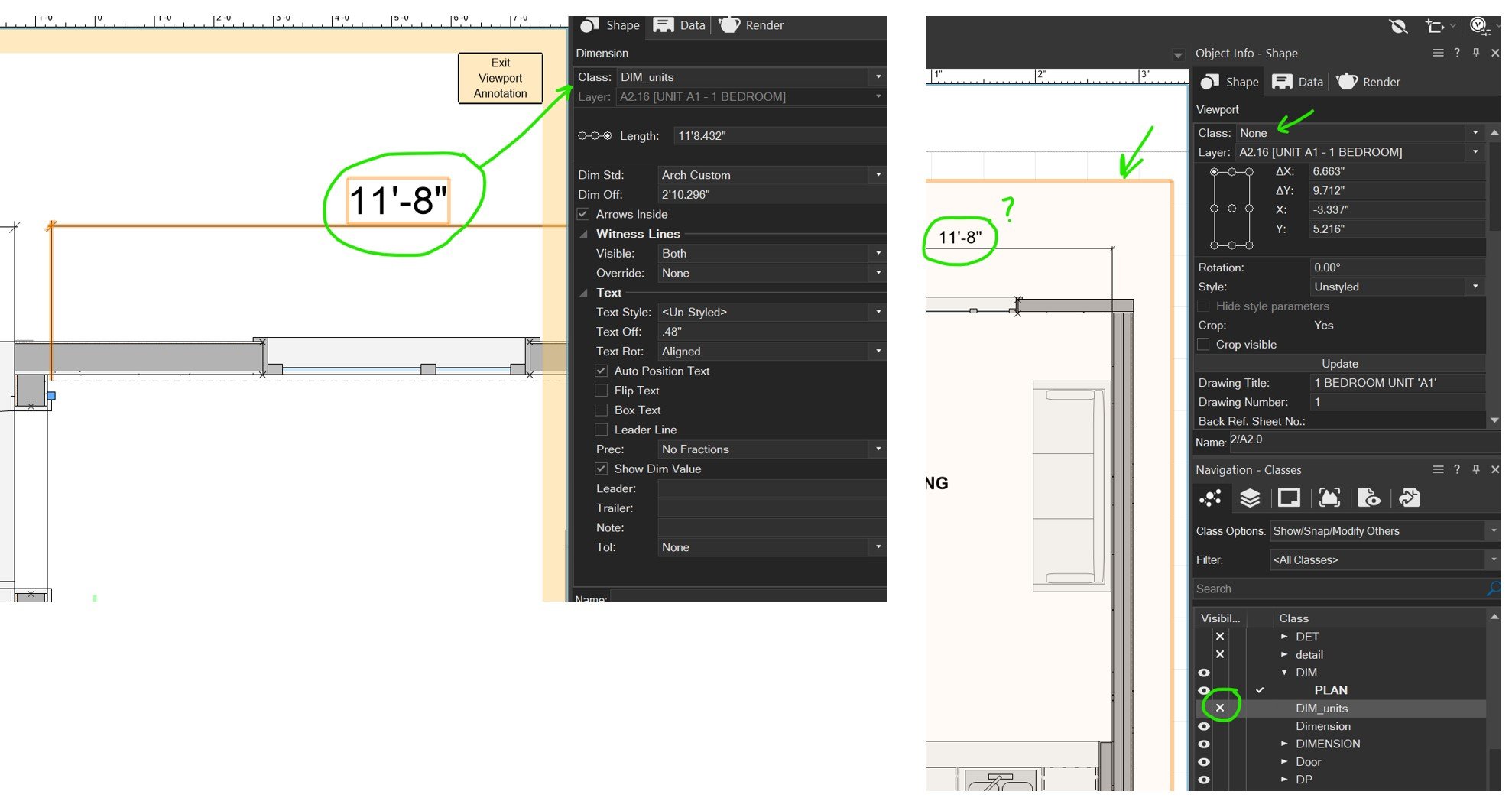
@Jeff Prince I tried all your suggestions and still no change. Please see my screenshots.
-
I need to make marketing drawings showing unit layout. One set of PDF drawings will need to show room dimensions and an identical set of PDF drawings will not show the dimensions. I'm new, so this is an explanation of my workflow: I've selected my viewport and click 'Edit Annotations'. I added my dimensions. I created a unique class name called "DIMS_unit". I select the dimension and in the OIP select the unique name from dropdown list. I then exit Viewport Annotations. If I want to export to PDF with no dimensions showing, I then go to the Navigation/Classes and turn visibility off for the unique dimension class name, but they are still showing. What am I missing?
-
Excellent, thanks.
-
Bingo! That worked. Thanks Jonathan.
-
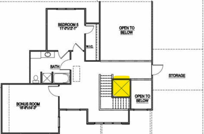
Hello, I'm a new Vectorworks user. I need to make marketing drawings for a multi-level multi-unit building. Each floor plan needs to be shown on a single sheet. How do I position the floor plan objects (2D Top/Plan) in the the same position for each drawing sheet? Currently each floor is slightly off in the viewport crop window. Basically, if I were to view the exported PDF, the floor plans should not move position as you cycle through the pages. Example, the center of elevator/hallway should not move position from page to page (see highlighted area on attached pic). Thanks in advance.