


Wood
-
Posts
87 -
Joined
-
Last visited
2 Followers


-
Does any buddy else experience VW blocking/delaying the finder's Task Switcher (command-tab) while processing commands? When VW hangs, I like to switch over and accomplish another task while it does whatever it's doing, but the app bogs down my switcher as well. No other apps do this, even when they've become unresponsive. I can click on a visible app and it will change focus right away. Any fixes? Thanks!
-
HoistExport.vwx Have a look at this. I'd always like it to insert on a specific class. I can currently control visibility with classes as I've assigned the 2D components to various classes, but I'd like the plugin object itself to default a standard class. I may also be imagining having been successful at this in the past. Thanks for your time!
-
Hello, I have hoist symbols that are configured to assign to a specific class, and they no longer do. They go to active class. I verified that the symbol options are correct and still have the specific class enabled. These same symbols have worked correctly in the past. I'm using the hoist tool to insert. What am I missing? Thanks!
-
Bringing this post back from the dead. I'm having the same issue right now, on some symbols that used to work just fine. Class is correctly assigned in the symbol options, but it inserts onto Active Class. This is happening with multiple symbols, and I'm using the hoist tool (It's a hoist). Did I change a global setting somewhere?
-
Steven, I reference complete VWX files with their own titleblocks very often, as I work with multiple departments in multiple companies. Referencing is the simplest way to push their updated revisions into my drawing, as well as not risk modifying their geometry accidentally. Your advice to use reference priority was right on the money! Can you share your other 'rules' for referencing? I feel like the VW guide is lacking here. This is the first I've ever used Ref priority, but I can already see its value. For those following along and wanting to solve the problem yourself: I reference in base symbols instead of importing, and that included my titleblocks. That way, if I revise a symbol, it's fixed for all of my other projects. In this instance, my symbol file had a lower reference priority than another team's file that I referenced as well, so it's titleblock superseded mine. It was a very simple fix to enable reference priority in the reference settings, and then drag the references into the correct hierarchy. Thanks again Steven
-
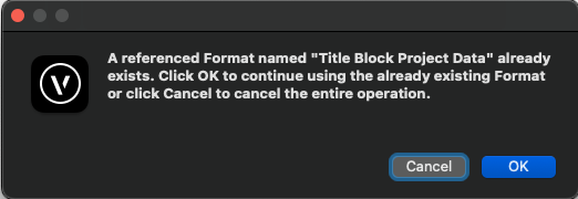
I've referenced a document in that included a titleblock on a layer. This block's data has messed up my Titleblock manager, and it has overridden all of my border, sheet, project settings etc. Where are these file Formats hiding, and how do I replace them with my native versions? Super frustrating that settings from other documents get imported when I just want some geometry out of a file. Is there something wrong with my workflow? This is the error I get when I try to import a good Titleblock border style. Thanks in advance.
-
Thanks @stayathomedad I figured out the Syntax for the lists, if anybody else is wondering: <WeightData isTotal="false" legend="" loadGroup="Cable" name="4 12/14 Socapex 2.24" ressourceName="12/14 Socapex" weight="2.24 lb/ft"/> 'WeightData isTotal=' False makes the makes your weight by a distance, as specified in the 'weight=' command. True makes it the overall load. 'loadGroup' sets the dropdown category. You must use an existing category. 'name' is the title of the individual load entry 'ressourceName' is the subgroup category. You want this to be the same for every item you want in a dropdown menu. Also, if you're having trouble finding the library folder, OS X is kind enough to hide it from you. Go to your user folder, right click, Show View Options, Show Library Folder.
-
Hi Folks, Looking to curate my saved set resource and arrange the collapsable lists, etc. I've found the XML file that appears to hold the data, but modifications there don't seem to change the VW dialog. How can I manage this data? Thanks!
-
Ah I didn't know about the blue symbol functionality. That works perfectly! Thanks! DW
-
Probably a silly question- Is there a way to make a resource that is a basic standard viewport crop square? When I make a viewport, I typically start with a rectangle on my design layer, and then use the create viewport command. I'm looking to create a library that has the standard sizes based on my end sheet layer use, e.g. Arch D in 3/16" scale, Arch E in 1/8" scale etc. I end up wasting a lot of time creating viewports in the wrong scale or not capturing all of my objects and then having to reconfigure in the sheet layers. What is the best workflow for this? Thanks!
-
Thanks Mark, I'll have a look!
-
Truss plug-in, draw centerline on ALL symbols
Wood posted a question in Wishlist - Feature and Content Requests
I'm looking to enable Draw Center Line, and also Draw 3D Only on ALL truss symbols in my drawing without first having to select every truss manually. Same request for radio buttons on the Hoist plugin. A little palette that would control all of this globally would be amazing. This may be easier to accomplish via script, but I'm not familiar how to make that happen. Thank you! -
Thanks for the detailed reply @jmcewen, and I use what you've described often. To stick with your comparison, I'm looking for the option to have that car on one side of the stage, and then show a later scene where the car has moved to the other side, or perhaps rotated on a turntable. Using the class instances you have described is definitely functional, and works easily with saved views. However, this ends up complicating gear counts if you're using those same symbols for inventory. In my case, I'm showing a bunch of different automated components that move, and if I duplicate them in alternate positions, I now have to manually adjust my gear pull sheets, or play a bunch of games filtering by class. Thanks again!
-
I just want to bump this. Once again the rigging team is left behind in functionality.
-
I'm sure this has been covered extensively, but not sure what search terms to use. I'd like to present symbols/3D geometry in alternate positions. Is there a way to create 'scenes' without duplicating all the geometry? I've seen this done with a bunch of different classes turned on and off, but that seems cumbersome. Can anybody point me in a direction to search and learn? Thank you!
