Search the Community
Showing results for tags 'site model'.
-
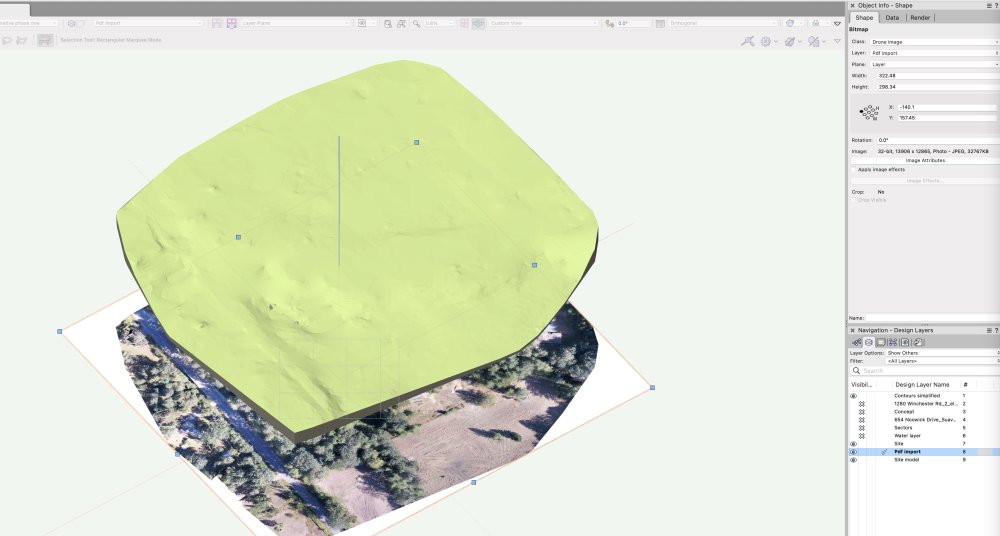
Hello everyone. I have just imported some geoeferenced contour data, created a site model as well as importing a high resolution image. These came from a drone survey. After watching a VW university video on Enhance site file collaboration with georeferencing I see that in VW 2020 (I'm using VW Landmark 2022)you can place a georeferenced image onto a site model. In the video example the image was downloaded using an ArchGIS service. I'm hoping to simply place my drone image onto the site model but I don't see any information on this. I'm assuming that this should be possible. I appreciate any feedback anyone might have. Thanks
-

'Proposed Contours' not working as expected in Site Model
nicovlogg posted a question in Troubleshooting
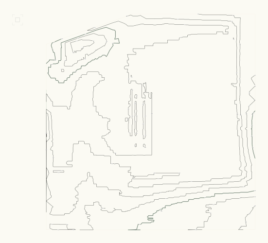
Hi all, I'm working with the 3D site model tools for the first time. I've gone through tutorials pretty extensively but haven't been able to find a solution to this issue. I have an existing site model, provided by the client. I'm attempting to model some new berms and swales on this model. When I add these in 'Proposed Contours', the model does not change. My view is set to show 'proposed' so it's not a phasing issue. Would appreciate any help. I can use the 'validate 3D data' tool and get an error, but there is nothing useful about a message that says 'something is wrong' - I need to know what it is. There are no overlapping lines that I can find. Existing contours Proposed contours - new in pink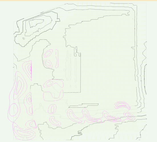
-
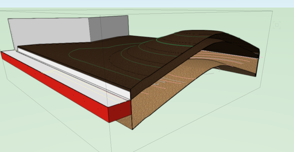
Hi All, We have a large scheme (in area rather than density). We have modelled the hard landscape using aligned hardscapes with site modifier stakes to get each hardscape to fall correctly with multi-directional falls. The site model will only update the proposed 3D topography if it is on the same layer as the hardscapes. When it does it displays too much moraying on the hardscapes to be useful. The hardscapes also do not cut the site model even when set to do so. Updating has no effect. Questions: Should I be able to choose a layer for the site model to align to? I thought this was a new feature but it doesn't work. I have followed this process but the model only aligns if on the same layer as hardscapes. Are there better, slicker, newer methods to create paved areas that can slope in multiple directions other than aligned hardscapes with stake modifiers? This method works well for us but aware things have changed a little in 2024. It takes a long time for the site model to update to align with the hardscapes. Is the model just too large an area with too many separate hardscapes? Screen grab below. Note the site model is not aligned in the screen grab. I have tried to split the site model into 4 to reduce load on VW but the edges don't meet cleanly where the cut in contours were made. Kind regards, Jack

-
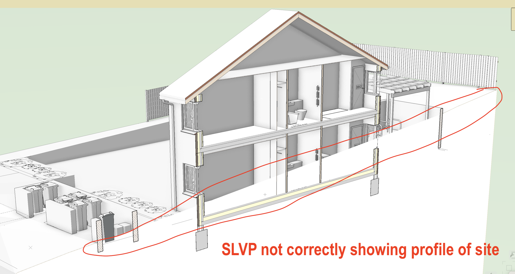
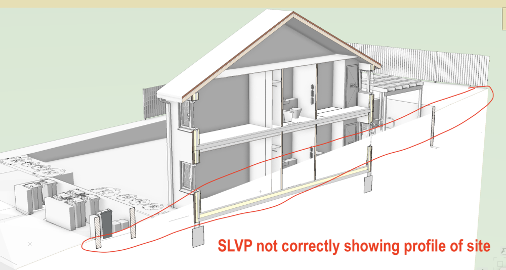
 I have a Site Model I've referenced into another file using Design Layer Viewport, but I have these two problems: The skirt is not showing in the referenced DLVP A Sheet Layer Section Viewport taken through the reference DLVP of the site doesn't follow the cut/profile of the site.
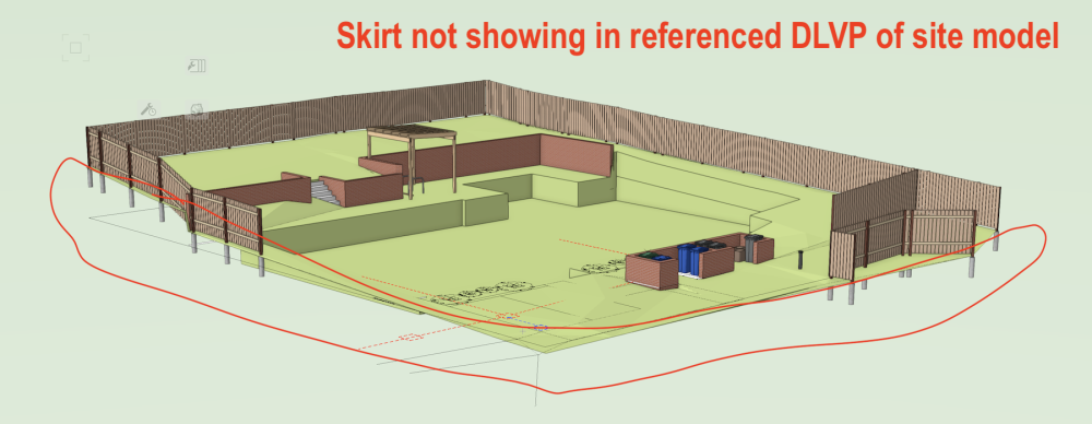
-
Hi guys, Can anyone tell if the export ifc works with site model? I'm working with an office that uses revit and the site model object is becoming a problem. Export directly a RVT file, the site model becomes a generic volume, that hardly "translates" to a terrain object within revit. The export ifc isn't working, tried a lot of variations on its settings, but the file comes empty. Anyone can give a help? Thanks!!
-
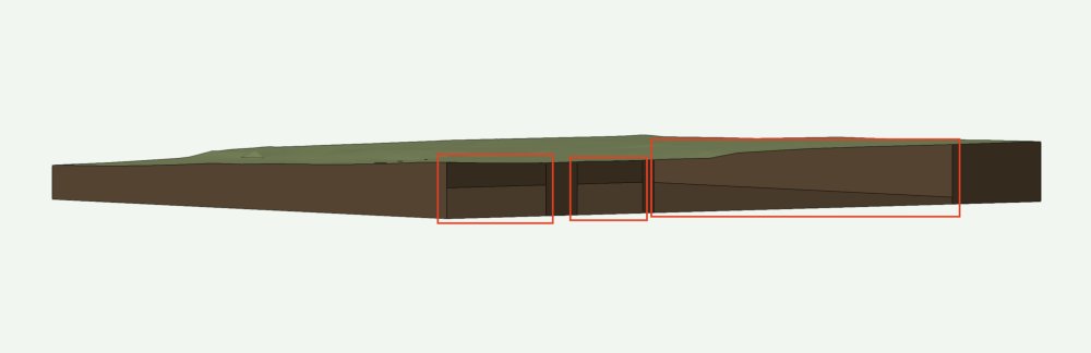
I have noticed that when I crop a Site Model I am getting holes in the skirt: They aren't always obvious to see + I'm not even sure how clear the screenshot is: the red rectangles are marking the holes. Basically bits of the skirt are missing + you can see inside the hollow mesh. Not nice. I exported the site model back to VW2022 + it's not happening there. I have no idea whether it's been happening since day one with VW2023 or whether it's a SP4 thing. Bit annoying...
-
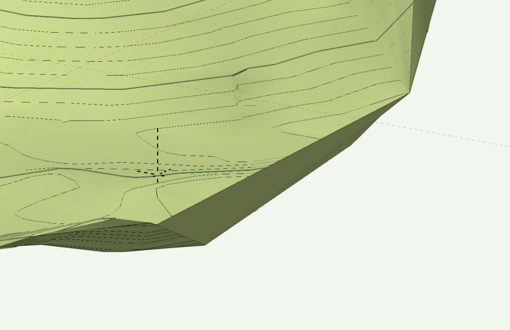
Hello! I'm attaching my file and a screenshot of the area I'm asking about. After I create the site model, everything looks good but for some reason, on one side, it creates a wall of stacked contours that have returned along the site model boundary. I tried editing the existing contours but they just end up going right back to where they were. I'm sure it's an issue with my source data or some of the settings but any help would be great. Thanks! 743298199_Untitled3.vwx
-
 I am experiencing an issue with Site Models where the underlying existing site data is being altered to meet the grade limit boundaries, when the Site Model picks up modifiers (The Grade Limit is set to affect Proposed only). The Site Model is on its own design layer, the Site Modifiers are on a separate layer, and all the modifiers are set to affect the proposed site only. The grade limit is also on the same layer as the Site Model. Can anyone provide assistance to resolve this problem? Is it a known bug? Tagging the experts here 😄 @Tamsin Slatter @bgoff @Pat Stanford Existing Site Model Problem with Grade Limits.mp4
 -
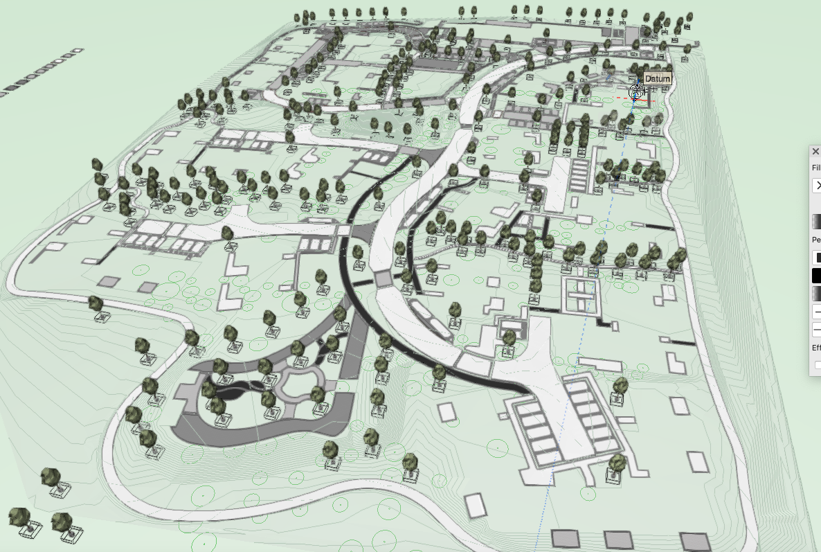
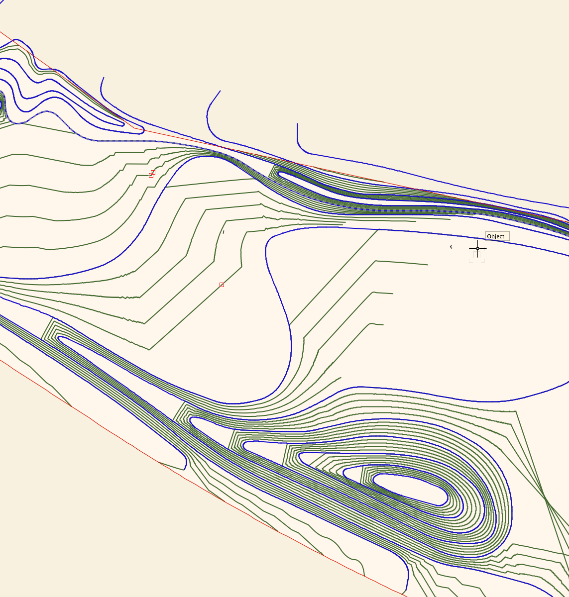
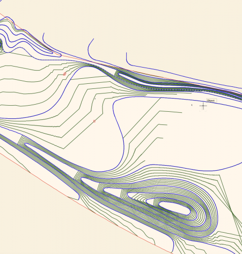
I'm wondering if I'm missing something in terms of the control we have over site modelling in Vectorworks. I've attached a screengrab of a site model I have created. Blue lines are the 3D polyline contours I have drawn and set to 0.5m height intervals, the green lines are the contour lines generated by the site model calculation by Vectorworks, using my blue lines as input data. I have two big issues with this output, namely: I want the model to EVENLY interpolate between the contour lines - for example on the hill to the bottom of the screen grab, I want the mounding to extend evenly to the left, I don't want flat platforms between each level. I want the contours to actually follow the curves I have drawn, and not truncate my contours in large angular lines!! (As seen in the middle of the screengrab.) Is there anything I can do, aside from draw contours at really tight intervals to reduce the visibility of the problem? Is this just how the site modelling algorithm works? I understand the need for a mathematical algorithm, but this results in a fundamentally incorrect site model I can't really use for anything in terms of BIM or production information, as it isn't giving me smooth grades. I'm sure I could fudge it for visualisation purposes, but I need an accurate technical model I can issue in IFC form to provide information for collaboration and also construction. I've turned on mesh smoothing in document properties, which makes the rendered model appear slightly less angular, and also turned on contour smoothing display, but I need an accurate model in terms of BIM compliance and I'm not sure I have this control outwith doing an excessive amount of contour drawing. Is Vectorworks the wrong software for this, or am I missing something? Any ideas or advice would be much appreciated. Lisa
-
 I have a site model if a area alone the water front. I am set contour data for areas on the water to be below 0 (negative levels) I will like this surfaces site model to render blue color to allow clearly differentiate between upland and wetland. Here is a link to the VW file https://www.dropbox.com/s/ro2ke5nzk1dqqh0/Hacienda_Delfines.vwx?dl=0
 -
Hi All, I'm struggling to understand how trees work on site models. If I give a tree a Z value it doesn't correspond to the site model level. For the tree Z0 is Z0 but the tree either comes in way too low or high when I give it the same Z value as the site model. Is it something to do with send to surface? If I tell the tree to send to surface nothing happens. Any help would be much appreciated. Jack
-
 Right now the stake tool required you to click in the elevation box, enter your elevation then place the stake. I know it does not seems like much but going back and forth to the elevation box then the drawing can be strenuous when entering hundreds of points manually. Having the possibility of a pop up box allowing to enter the next elevation after each stake being placed would be a nice and simple addition. Or Just being able to hit the Tab key to enter the elevation box maybe. Just something that give the possibility to skip going to click in that tiny elevation box would be nice. Thank you kind developing team
 -
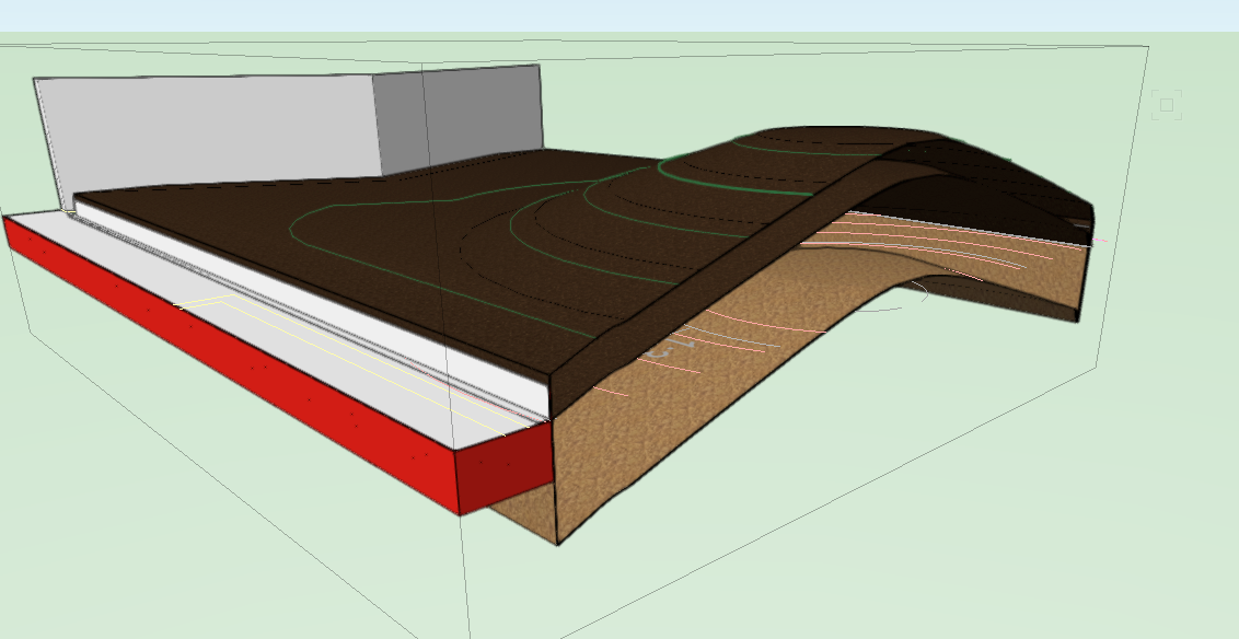
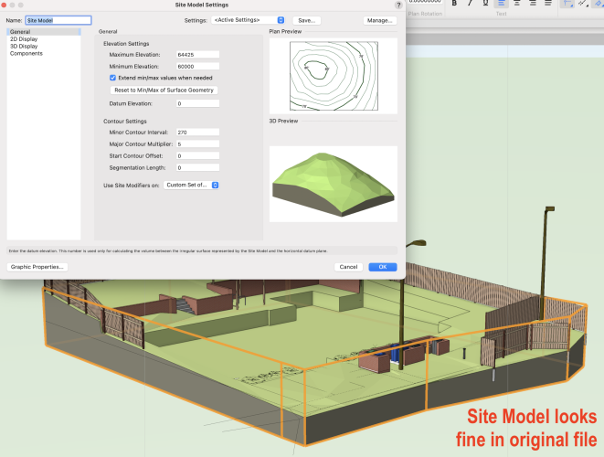
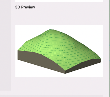
Hi All, this is similar to older posts I've raised but different as it refers to Site Models specifically. Our required soil build us consist of 300mm topsoil over variable subsoil depths. Is there a way to represent this in site model components? The mound is on a roof so level bottom surface. Image below. The site model 3D preview in the dialog box implies you can have a flat base and variable depth soil. I want it to look like the 3D preview only be able to have the top 300mm as topsoil and the rest subsoil. Thanks, Jack
-
 When using the stake tool, you currently have the option to "Set Elev to Site Model" as a way of creating spot elevations for a grading plan. This is great when documenting the surface of a site model for high points and such, but often the elevation we are looking to document is actually a feature such as finish surface, top of wall, bottom of wall, etc. These items are placed on top of a site model, so a stake object trying to query their top elevation will only return the elevation of the underlying site model. There should be a way for the stake tool to recognize modeled elements in the drawing to pull this information into its reference.
- 21 replies
-
- 12
-

-
- site model
- grading
- (and 2 more)
-

Saved View, Site Model status
Benson Shaw posted a question in Wishlist - Feature and Content Requests
I tried to make 2 saved views, one showing DTM exist, another showing DTM as proposed. I don't think this is possible, because update needed. But would be nice time saver, for instance comparing effects of site modifiers to existing. -B -
Good afternoon folks, I've been banging my head agains the screen for 2 hours now trying to cut out a basement from a site model. I've got a 3D polygon in the outline of the basement footprint set to the proper elevation. If I convert it to a Pad site modifier, the ground slopes into it. I need the edges of the cut to be vertical. I've played around with a Grade Limit 3D poly to the same shape as the basement footprint but it's not really doing anything. Does anyone have a method of cutting a basement out of a site model? This file is in VW 2021. Thanks folks. - Dylan
-
Hi all, When i'm doing a site model and then insert my building into the site model with foundations, floor slabs etc, how do you "subtract" these items from the Site model?? so when you do the sections it shows properly. I've attached an example of what i'm explaining here but used a slab mimicking site model.

-
Gradient Cut Fill Site Model Visualization
ericjhberg posted a question in Wishlist - Feature and Content Requests
It would be awesome if you could generate a 2-dimensional visualization of a Site Model's cut/fill, but instead of just static Cut = Red and Fill = Blue...you could assign a gradient for each that could color the site model based on cut severity or fill severity. For example a White to Red gradient for cut that the greater the value of cut, the deeper the shade of red. Additionally a White to Blue for fill that the greater the value of fill, the deeper the shade of blue. This would be an extremely useful way to visualize site models. @Tony Kostreski @Eric Gilbey, PLA @Vlado @bgoff- 4 replies
-
- 4
-
-
- site model
- landmark
- (and 2 more)
-
I'm having a problem. I have a site model. It has modifiers attached to it defining roads, sidewalks, new contours, ect... When I go and try to change the class it sits on, the material, or texture, defining the surface gets changed. Why is this happening? There is no texture or material assigned to that class. Please see attached video. Thanks, Rudy Beuc 2021-09-30 23-11-24.mp4
-
I'm having difficulty sending plant objects to the Site Model elevation using the Send to Surface command. Meanwhile, simple symbols send to surface in replacement of the Plant Objects without problems. I'm in VW2020 and it's been awhile since I've tried this command with plant objects...long enough to question if Plant Objects lost this functionality in VW2020 going forward? Thanks.
-
There should be an option to Lock In Place for Site Model objects, similar to Referenced Viewports. I can't tell you how many times I'm panning around my site model and accidentally grab it and move it...sometimes without noticing. Of course, you can Lock a Site Model, but that doesn't allow you to perform updates to it either.
-
Hello community, Am trying to send to surface (site model) hardscape object using stake objects in hardscape surface modifier..but with no luck... How we can simply send to surface hardscape object as is possible with road object? I thougth it might be very easy to do this kind of operation with all of aligned slabs options but cant find the right steps to do so. Hope there is way to do this automatically without need to position stake objects individually that is case when site is quite uneven. Thanks.
-
no responses

-
Building model as site modifier
Christiaan posted a question in Wishlist - Feature and Content Requests
Why do we have to manually cut Site Models to fit around our building model? Why can't the building model be the modifier? -
I have an exceeding basic OS survey which I want to create a 3D model from. It has very few 3D locus points on the paved areas and some contours on the grass areas. I have converted the contour lines to be recognised as contours in Vectorworks and have said they are to effect the existing site model. Now when I select everything and choose to create a site model it just uses the locus points not the contours. So I have added on more locus points following the contours and in other locations where I know there is a kerb etc which is not shown on the levels information (copying and pasting original ones and changing the height in the object info to the height I want) But when I then select all and try to create a site model from survey information it doesn't use all the points. Some of them seem to be incorporated, but not all of them. What am I doing wrong?? SiteModelData.pdf