All Activity
- Past hour
-
You probably meant the ‘seating’ tool.
-
I know this is basic, but cannot figure it out! I'm trying to create a custom report that includes the plant symbol. I have tried adding "image detail," "image misc," and image plant form, all to no avail.
-
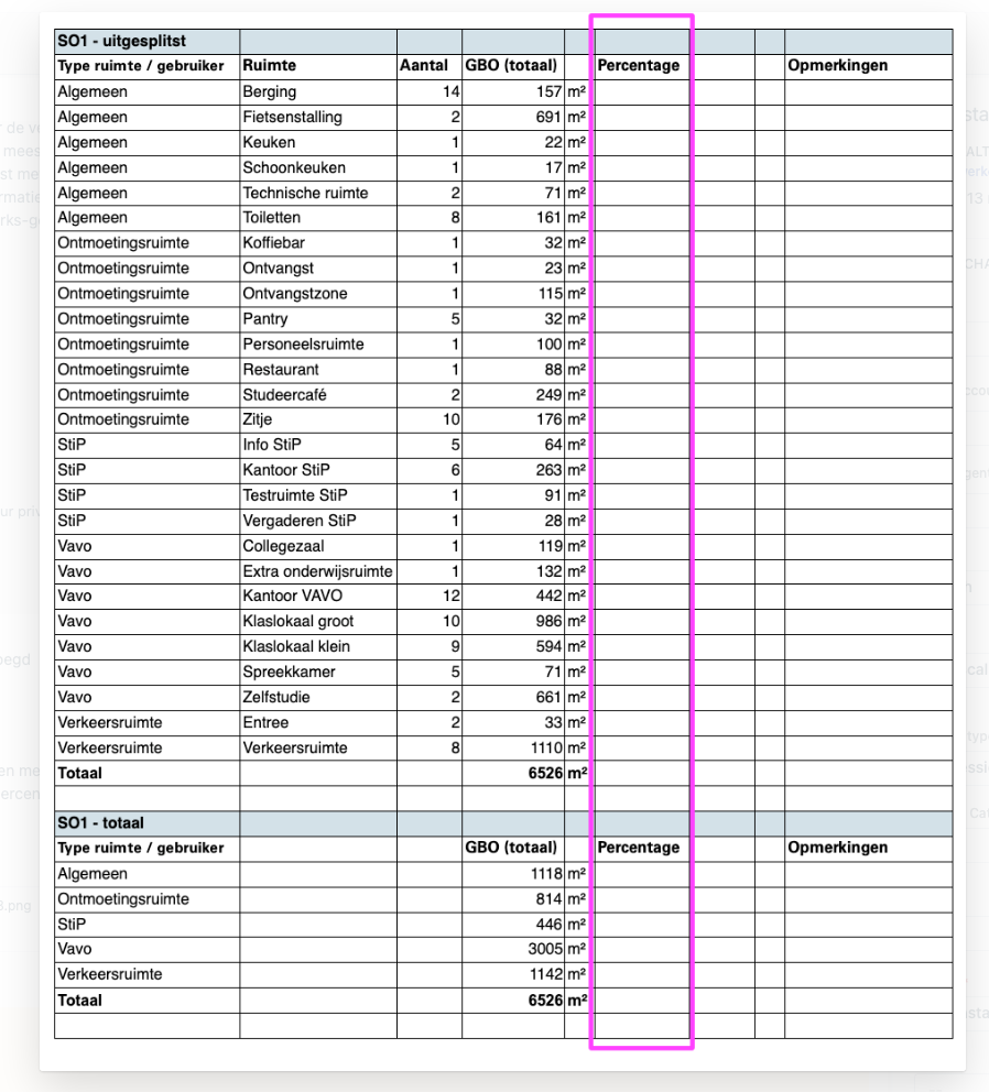
No, I don't think this works, because the sum of the areas is in a data row, and then you get the repetition of what is in the data row in all cells below it.
-
 Hey y'all. i was wondering if you had any insights into why my model is giving me such dark spaces when I transition from Final Quality to Shaded. I've included a screenshot where you see the final quality being rendered in the middle versus the shaded quality in surrounding it. Any insights? There are currently 5 lighting objects with 3 overheads at 70% and 2 under lighting at 30%. I'm operating on windows, latest release.
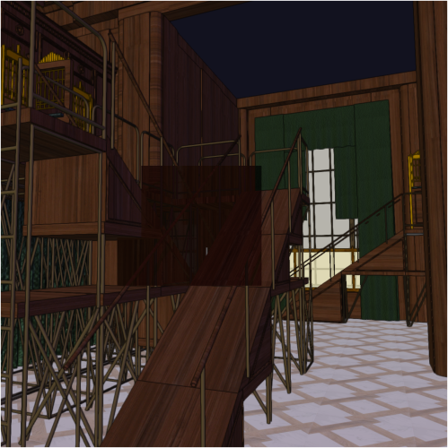
-
 Thanks, Do you suggest putting a title block over the drawing in a Design Layer and the creating the viewports from that? Would I then still get the grid numbers and letters on my Detail Viewport or just the lines of the grid?
 -
I think you would have to manually enter a formula such as =A2*100/[sum of areas] in column B. I don't think there's a way to do it automatically in a database i.e. without entering the sum of all the areas manually. But let's wait to hear what the worksheet experts have to say.
- Today
-
 Rocket63 joined the community
 -
If I have all the areas of the space in column A, how can I display these areas in column B as a percentage of the sum of all areas.
-
 If I understand your desired outcome correctly, you can put grid lines on a design layer to solve this problem.
 -
Draw a cross section and use Extrude Along A Path (EAP) in the model menu. There are lots of examples of this particular problem here on the forum. Then, use the searing tool.
-
Have you gone through the seating tool options already?
-
@Peter Telleman The reason why the Christie is green and the Tomcat grey is that Christie has given us the structural data for their trusses and Tomcat refuses to do so. Any truss that doesn't have the structural data is by default set to use the rigid crosssection model. This means that it calculate forces acting on it and passing through it but can't calculate how it reacts to those forces, so no deflection or bending moments for example. I had a look at the symbols and I think the issue is with the 90°corners. I'll dig a little deeper when i get a minute and let you know what I find
-
Have you tried the Stage Plug tool? It echoes the Polyline tool in that each instance can include a mix of straight faces, curves, and arcs.
- 1 reply
-
- 2
-

-
@Dano Parke - quick question, as I can't see any benefit in your workflow. I'm prob missing something, but it seems overly complex. Don't you end up with a handful of walls all very similar - Lets say a design based on 4'',5",6" or others very close to the same dims. Sketch layout looks ok, but you've no (quick visual) control over which wall you used unless you start clicking them in turn to find properties. Wouldn't you do better to adopt a collection of 'most used walls'. Each can have some degree of identification for you in your chosen design use (quicker to choose and use in the layout) and then (my assumption would be) you then choose 'hide details' to provide plain grey (fill) walls for presentation to client? Or your particular field doesn't have standard walls??? Then there's windows/doors????
-
Can multiple single line text be combined into one multiline text box?
-
 kbydesigns joined the community
 -
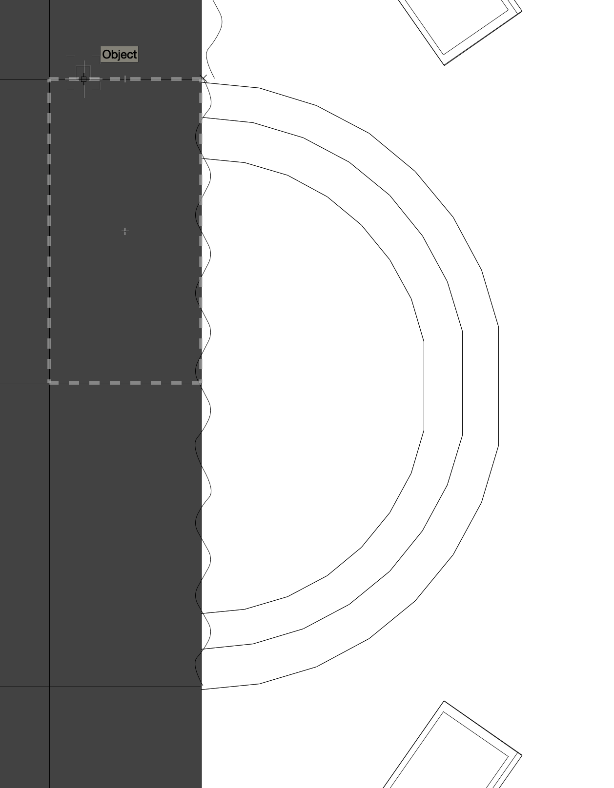
Hi, I have a stage that includes a round stage in the front and some triangles. I just cannot figure out how I shall do the setup so VW understands I have the risers for this. See attached files. Thanks in advance!


-
I'm wanting to Map user fields as follows: User Field 1 – Act 1 Focus User Field 2 – Act 2 Focus User Field 3 – Act 3 Focus User Field 4 – Act 4 Focus User Field 5 – Location User Field 6 – Group The mapping works, but when I try to change the names of the user fields in Vectorworks to the same inside of spotlight preferences. it removes all info and doesn't then let me re map that field inside of Lightwright. Working on VW 2024 @Lightwright Thanks
-
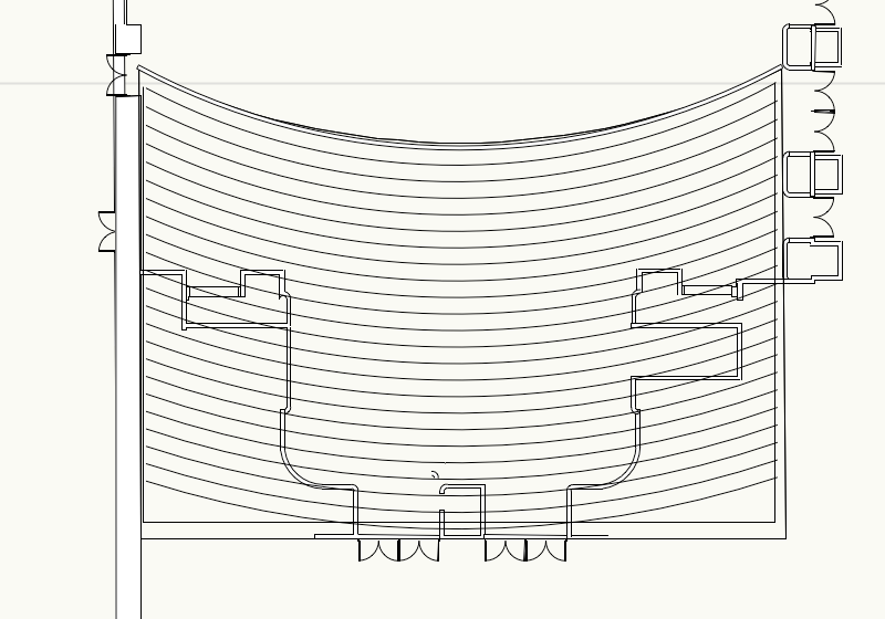
How would I go about making a stepped seating section? It would look like this, but I can't work out a) how to extrude this as a) a gradient, b) how to put the seats in after I have done that. Thank you, Iain
-
Thanks, I think it would be universally usefully for locating detail in any of the uses of vectorworks not just Entertainment. 👍
-
Hello @t-bud, You can set up an equip item symbol with the linked texts set up as you wish. Then you can use this symbol to create new equipment items either by drag&drop from the resource manager or by double clicking on the symbol and placing it with the equipment item tool. That way you will have your linked texts set up only once fro this symbol. Let me know if this helps. Best Regards, Nikolay Zhelyazkov
-
 Okay I get it. Currently this is not possible with the title blocks, unless you manually add the grids instead of using the TBB grids. I will add a wishlist item for this. Thanks for the feedback!
 -

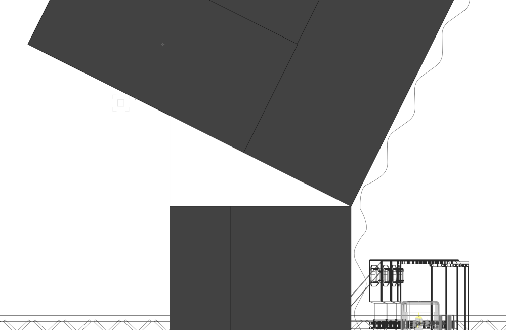
Calculating a specific surface area (3d) within the site model
Carol Reznor replied to Dave Norton's topic in Site Design
@Dave Norton Or as a Hardscape (style) with a Draped config ... the surface will have a consistent thickness - and by checking the Cut the site model you will also see the result on your Site model and for finetuning you can also change the datum if needed to (top or bottom...) -
hi @Gal Hard to tell just by looking at a screenshot... It looks like the Site model is coming up to the cracks... Is your road in one piece or are these segmented parts that don't fit together 100%? Also I see what looks like a grade limit to which the Site model wants to grab to... What is the purpose of that grade limit and is it set to Existing or Proposed? Also hard to tell what is going on on the left side as it appears the Site model is at times interfering withs the darker grey 'wall?' I presume more could be said when it is more clear what is going on... by sharing the file?
-
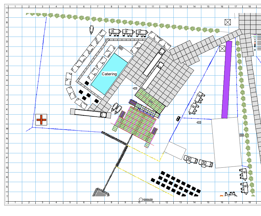
Hi @Nikolay Zhelyazkov, I've put two rough screenshots of what I would like, I have a Sheet Layer that has a Viewport of the entire event site. From this we would make a set of grid references for suppliers to locate their trader positions, for first aid to know where they are going and security to know their positions etc. I've also just placed a Detail Viewport from this drawing on a second sheet layer for the main stage only but as the grid is specific to the sheet layer, it means that any of the grid references we make don't work for this sheet. I'd like the grid to start halfway through number 20 and finish halfway between number 30 on the horizontal and be between S and Z on the vertical axis as it does on the main site sheet. Is there a way to make it so that every Detail Viewport I make can have a grid that lines up with the grid that the Detail Viewport is taken from? Many thanks, Matt.

-
Hi @Rebecca R Your own plant catalogue is that based on a txt-file or is it a Filemaker type? If it is text based I find it helps to open it in a spreadsheet application. Then add a Header row to your file. Then insert the 'More data'-fields as header and rearrange the columns so that they have the same order of the fields as displayed in the Plant More Data. Hope this helps
-
Hi @Matt Overton Thanks for your input! Our forum is already a key feedback hub and additionally we have the RoadMap page. While G2 is an additional platform, providing feedback there is optional. We're considering your suggestions for improving engagement and inclusivity. Thanks so much!