VIRTUALENVIRONS
-
Posts
1,023 -
Joined
-
Last visited
12 Followers

.thumb.jpeg.48a6fdc44e48c98b8e1b507e86e57e95.jpeg)


Recent Profile Visitors
4,990 profile views


-
Hello to the both of you. I would be happy to write a tutorial or two, but there are so many ways to create free form shapes that I don't know where to start. Is it the basic shape or highly detailed, etc. Please advise.
-
I am not an architect, but as you may still be searching, perhaps I can point you in the right direction until one chimes in. First off, the dwg. is wonky. On paper, the walls are not parallel and the circular element is also not concentric, but are they in reality. I would look to extrude all contiguous elements in one action, so there is no need to join them after. spend some time with the following. Add Surface Clip Surface Intersect Surface Three point circle (Square tool) - Three point rotated.
-

Vectorworks 2024 drifts away overnight
VIRTUALENVIRONS replied to VIRTUALENVIRONS's topic in General Discussion
I would always do the same when I was working. My main computer and two external hard drives. The current work on DVD. I am going to migrate this back to "Drifts Away". I have been testing something. Up until I posted this question, I had been using a "Sleep Corner". I forget why as I have always used "Sleep". I have left VW's on over night a number of times and it has not "Drifted Away". -
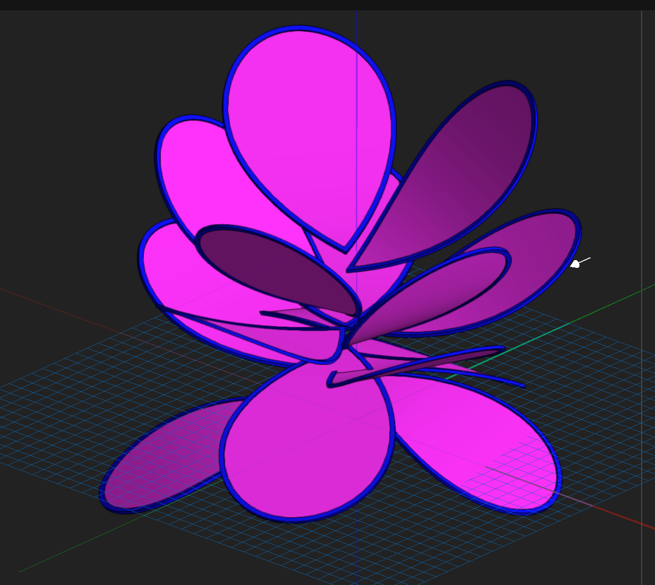
Just Playing. Never thought about flowers in VW. The power of VW's 3D modelling is largely unknown.

-
This thread appears to be split. It has the same header, but I don't see this on the other thread. You can see the other answers on it. Anyway, on this thread. There is another way to model in VW's that is like Subdivision, but is not. It is all continuous NURBS surface with the inherent follow on use of all NURBS tools. It does not appear to be well known, if known at all. The flower below was make without using the NURBS tool palette.

-
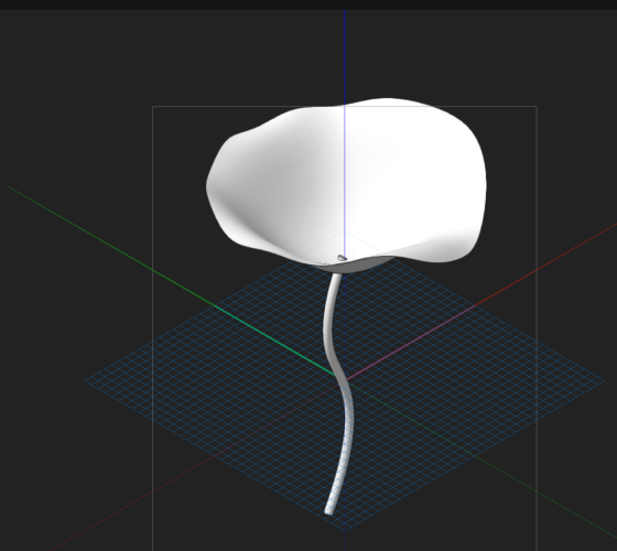
Here are the three files I made this morning. It is not hard to make these, but unfortunately each step is a tutorial in itself, unless your NURBS Kung fu😀 is fairly advanced. The white flower was very easy to make, if you like, I can do a tutorial on that one. Paul NOTE: The file with multiple petals SNI_1_FORUM. It has one petal on layer one registered at zero in all views and the entire group on Layer 2. FLOWER 2_FORUM.vwxFLOWER_FORUM.vwxSNI_1_FORUM.vwx SNI_1_FORUM.vwx
-
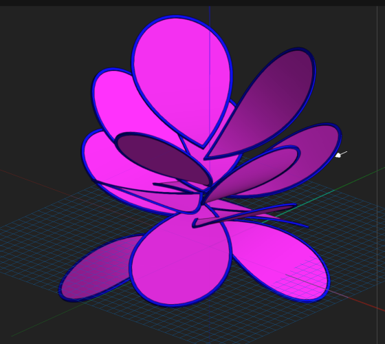
For such a nice comment, you get a Rose, If I gave you the three files which includes this one, would you be good to go. I can make others for you if you need some tweaking.
-
....And this one
-
Something like this. If so, you can have it if you want it. You will have to texture it.
-
HOW TO PLACE OBJECTS ON CURVED SURFACE?
VIRTUALENVIRONS replied to Tayloj986's topic in Architecture
Try this. It allows you a level of interaction before committing to nonparametric objects. Watch this video and come back if you have questions. -
HOW TO PLACE OBJECTS ON CURVED SURFACE?
VIRTUALENVIRONS replied to Tayloj986's topic in Architecture
From you image it was unclear whether you had a curved or facetted surface. Either way this will work if you want to use text and be able to edit the text after it has been curved. -
Extrude along path on different planes
VIRTUALENVIRONS replied to ChollyO's topic in General Discussion
Good stuff. The car tutorial is ten years old now. I made that with 2015....I think....so long ago. I shared it with Vectorworks at that time. They liked it also, but only as an outlier of sorts. -
Vectorworks 2024 drifts away overnight
VIRTUALENVIRONS replied to VIRTUALENVIRONS's topic in General Discussion
@LvLd Thanks for that. I will remember that next time it happens. -
Extrude along path on different planes
VIRTUALENVIRONS replied to ChollyO's topic in General Discussion
Clarification. This was brought to my attention via the Forum. The channel listed on my posts is relatively new and only has 50 or so Subscribers, so It could not be monetized. My main Youtube Channel below (Virtualenvirons) has over 4000 subscribers and is also not monetized, but it could easily. I don't, as it would cheapen the venue, but Youtube does advertise on it. Anything from Boeing to Elon Musk. On the Vectorworks/CINEMA 4D combination. I have never posted this channel as it would raise more questions than answers about VW's NURBS modelling. Except characters, one jet and one car, everything was modelled in Vectorworks and rendered/animated in CINEMA 4D https://www.youtube.com/channel/UCGRlY9Y3kHy18b6MgtB6Hbw -
Extrude along path on different planes
VIRTUALENVIRONS replied to ChollyO's topic in General Discussion
@ChollyOThere are many tutorials on how to use the tools, but few on how to apply the tools to achieve a goal. I don't know if you looked at my Youtube channel link (not monetized) that is below. It has a number of tutorials that last between 5 and 25 minutes ranging from beginner to intermediate. Below is an easier example. NURBS modelling is a trial and error process, you must keep this in mind.