Monkeypuzzle
-
Posts
43 -
Joined
-
Last visited
-
Hi all, I'd like to be able to show the cable end markers but not the cable runs as they clutter up my final plans. How do I achieve this? If I turn off the cable class I loose the end label even though its on a different class. Thanks.
-
MVR export from Vision...
Monkeypuzzle replied to Monkeypuzzle's topic in Vision and Previsualization
Okay, I can do the final editing in VW but it's easier in Vision and more importantly, I can prove the file easily. Is it something in the pipeline? I've just looked to see if I can import a v3s back to VW and that doesn't seem possible. As Vision is a VW piece of software, its seems odd that files can only go one way. -
Is this possible? I want to send .MVR files to guest LDs visiting my stage at the next festival I'm working on. I generally get the stuff built in VW for planning etc then export via MVR to Vision. I then do some final edits here as I can see things live from my desk. I only seem to have the .v3s though. Cheers, Matt.
-
Hi, This is a bit out off my comfort zone so I'm going to need a bit of hand holding on whats probably a really simple problem. I have a photo of some tree's that a client has asked for some LED tape to be put around as an outline and they want a (very) rough mock up of this. I'm not very familiar with any of these parts of VW so... I import the image into a new file, Draw roughly where I think the tape will be with a 12mm double line ploygon and extrude this by a few mm to mimic the tape. I then create a texture with reflectivity set to "Glow" and expect this to add some additional brightness to the image I've imported... Of course it doesn't because I'm going about it completely the wrong way... so how do I do this? Many thanks in advance Matt
-
Ace, many thanks, I watched quite a bit of the tutorial and think I missed this bit. Matt
-
Hiya, I've just started using the cable path tool and cant seem to make it work the same way it does in the video. In the video the cable I'm drawing exits the cable path at points all along its length, mine only exits at the start or the end. What might I be doing wrong? Many thanks, Matt
-
I'm pretty sure this gets asked quite often, I've had a basic look around the forum but can't find a good answer. I currently use a MBP 2017 2.9 i7 with 16gb and a Radeon Pro 560 4gb for my VW work. It's mostly using Spotlight and Vision but the models I'm making/being given are getting pretty busy and slowing the machine down. Whilst I'd like to keep the MBP as a portable solution I need to make a desktop machine that I can use at home. My budget for MB + CPU + cooling, GPU, PSU and RAM is in the region of £1k. I know this is small and if I have to push it a little to get a sizable gain then I can but only if it really makes a real difference. What are peoples recommendations? Refurbs considered... It's been nearly 15 years since I last built up a PC system having moved across to mac so I'm very out of date. Whilst I'd love to buy a new M2 machine it's just not going to happen so any suggestions greatly received. Many thanks, Matt
-
Hi all, I'm really struggling with the new cable tools. Everything worked fine for my needs previously but this added complexity has just thrown me. The current project is an illuminated trail through a park, I have somewhere like 300+ ground based fixtures and there is no way to make an exact cable plan given the nature of the terrain in the park but getting an idea of rough cable numbers would be great. A few things: Is there a tutorial somewhere that explains consumer/inputs and outputs in fixture symbols? Some of the fixtures I'm using don't have them built in so I need to learn how to add them. When I create a cable work sheet, it wont recalculate like other sheets from the drop down menu "File - Recalculate current worksheet", I need to close it and start a new one to get an update. Cable lengths... so if I have a cable of 8.8m then rather than suggesting a 10m it places a 5m, a 2.5m and a 1m. This is with "fewest parts" selected. Given that its all outside and I'd rather have 1.2m slack rather than use three separate cables, what do I do to make this work better? When I add a new cable, I'm always asked to assign an output and even though I select "Always use next free" I keep getting asked, even when there is only one output. Very annoying What is "insert distributor before each lighting device"? If I create just one 10m cable between two fixtures and then create a cable parts list, I see one x 10m and 2 x 1m. I can't see the 2 x 1m on the drawing. Any idea where these are coming from? Cheers, Matt.
-
Brilliant, thanks very much. It'll take me a while to make my own, each with the colour code the company I do most of my work for but I do see the value in that. Would it be possible to create a saved set inventory for each hire company? I don't want to trawl through turning on or off loads of cable lengths/types depending on where my kit is coming from on a particular show. I never use Harting or Shucko or many of the other types and I know I can turn them off but an opt in (to a user set) rather than opt out of a general set would be really handy.
-
I use 1m, 2.5m, 5m, 7.5m 10m, 15m, 20m and 30m lengths of 16a/1, True1 and signal. How do I get the 2.5m, 7.5m, 15m and 30m lengths into the new cable tool? It was easy before. Now the help feature just says: Advanced users can edit, add, or remove items from the cable parts list. Edit the symbols in the Cable Tools folder in the [User]\Libraries\Defaults folder. Click Update in the Manage Cable Parts dialog box to refresh the cable parts list. I've followed this to an XML text file that I've gathered is where the info is held, do I need to add through this and create the cable I need this way? Many thanks, Matt.
-
I've just updated to VW22 half way through a project as one of the other workers is using it. Our base file was created in 21 and when we export or publish sheet layers they come out twisted and with lots of the information rotated almost randomly. The sheet layer looks fine on the screen within VW but when I export it it goes wrong. CBP v12.vwx
-
Importing GDTF and Vision fixtures
Monkeypuzzle replied to Monkeypuzzle's topic in Vision and Previsualization
Thanks, that's all great. I'm going to have a look at GDTF files a bit better tonight and compare the ADJ I have that does display the gobo correctly and the Chauvet that doesn't and see if anything is different. The ADJ also has a problem with the shutter channel as it doesn't seem to respond correctly to the "Open" section of the range. GDTF seems great, the personality I made for the solo works perfectly with the zoom functioning as it should. As for the GDTF builder, it seems that this isn't yet available for my Mac, is this correct? Oh and why are focus directions lost when I use GDTF fixtures? Cheers, Matt -
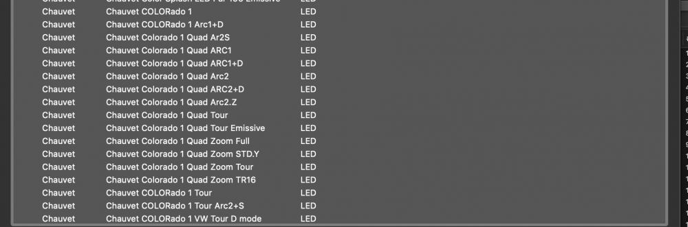
Hi all, hope things are going ok out there... I've got a bit of pre vis to do for a small venue and I'm struggling to get it all happy. The fixtures are: Chauvet Intimidator Spot 260 which I've had a fixture made by VW and sent through. This has come with the GDTF from the GDTF website it seems. They work as expected in Vision apart from the gobo which seems to do nothing. I've checked the GDTF file and it seems okay but I'm pretty new to it. Any ideas? ADJ VIZI Beam 300. These again came from VW and seem to work okay. Chauvet COLORado 1 Solo for which there is no VW or Vision fixture so I've had a play with the GDTF builder and made something that seems to work apart from when I move the zoom, every now and then the beam looks like it has a ring gobo in it. Also using the GDTF fixture doesn't seem to carry through the focus information either. If I set it to a "Solo 2" (as a VW fixture) then the focus point is correct but it's missing some features like zoom. Oh and VW programmers, please, please, please, put a column in the fixture selection box showing the number of channels each mode uses. I know there are many ways of checking once I've loaded the fixture but when there are 6 or 7 personality types and they may or may not be correct just knowing how many channels are used in each personality would be ace. And...... one final question, when I load an MVR file, if I select "use GDTF" instead of vision, where does Vision look for the GDTF fixtures? I think I've worked out that when I select "use Vision" it will use whatever is selected in VW. Is this correct? Sorry, loads of questions there, any help much appreciated. Matt
-
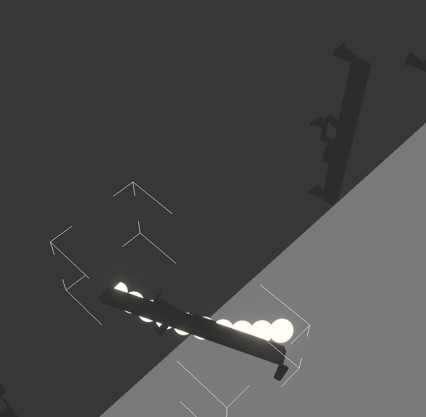
Sure thing, here's the file, I've just tried to reproduce it but it doesn't even want to rotate the fixtures. When selected, the light goes out and it doesn't move. That would be a shame about the lack of gobos on ETC lanterns as they're pretty universal world wide. I hope it's something simple.RNCM v10.v3s cheers
-
Cheers, That's really appreciated, I found the glitch and it was certainly my fault, I had the x axis rotated 90* so everything was out. I did initially have a play with the rotate 3d option and whilst the light moved, after wiggling it around a bit, I stopped and not a single part of the light lined up, the clamp was over here, the feet were over there and I couldn't seem to get it to line up with the plane I wanted. The attached pic shows one after playing with rotate 3d and then setting all the rotate parameters to the same as its neighbour. As for gobos. I can't seem to find where I would select them... sorry, me just being blind I reckon. In the properties window there's an arrow just before the "Colour Wheels" option which allows me access to the gels. For all the generics in my model (etc 15-30 led and tungsten and Strand SL's) there is no arrow next to "Gobo Wheels" text. Thanks in advance.