All Activity
- Past hour
-

Textures - Porcelain tile 1200 x 600 in 1/3 Bond
Tom W. replied to Stu Wilson's topic in General Discussion
Have you tried the Mosa Pattern Generator? File > Import > Import Mosa Pattern... Or mtextur (File > Import > Import mtextur). -
Hi All, Despite 90% of all existing textures being US based companies and 30000 different types of irrelevant block paving.... where do the UK market/designers find suitable textures relevant to our market and easily downloadable. Any help would be great..
-
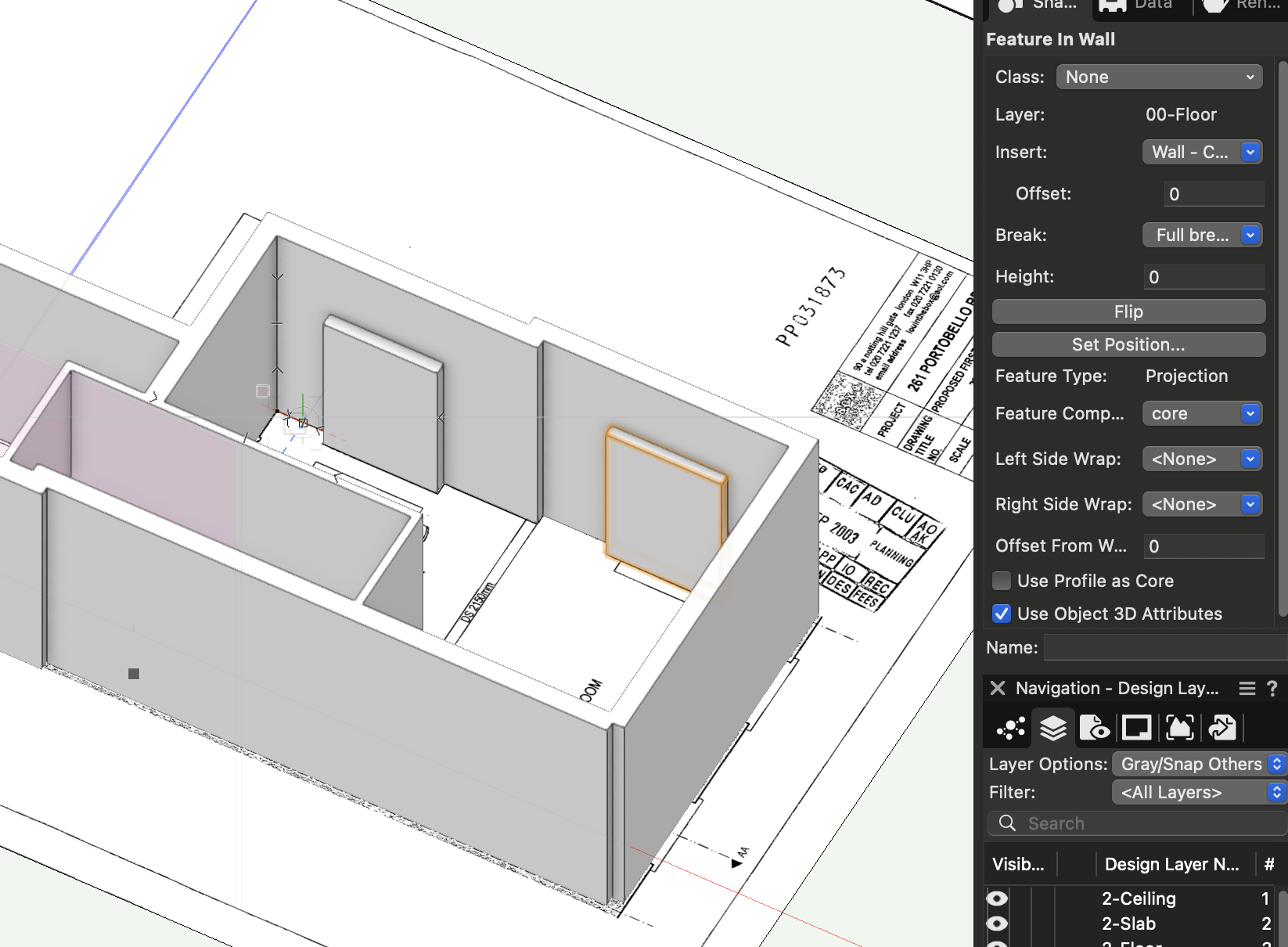
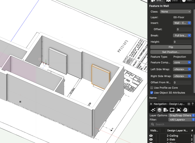
Hi, Sorry I may have missed something, when inserting features in wall within wall styles that are bound to story level, the features in wall aren't following the story height they appear to stich to a fix height instead. When selecting the feature within the OIP, the offset from wall height is set to zero and I don't seem to find an option to link the feature height to the story level. Any idea on how to fix this please? It is quite tedious because features in wall repeat throughout the stories but stories have different heights. Many thanks Federico
-
 ニシカワ joined the community
 - Today
-
 Petita Grill House joined the community
 -
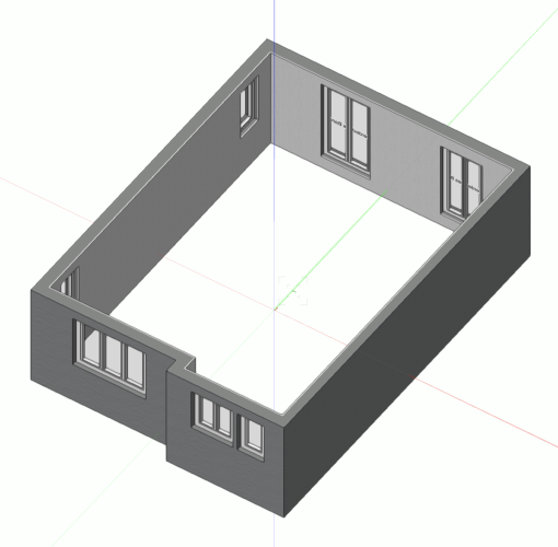
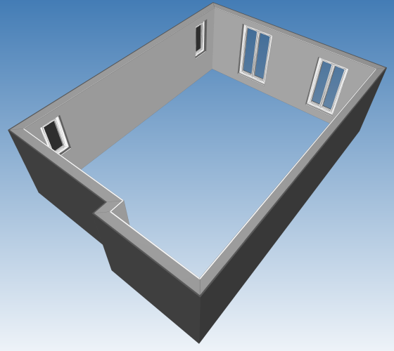
I have a problem with exporting some simple walls with windows. I first came up with the wrong representation inside DiaLux and thought this is DiaLux problem, but the same happens when i import the ifc file into bimcoolabzoom. See the screenshots from vectorworks and bimcollab. Windows and openings are completely missing and some have their opening only when viewed from the inside of the geometry. Known issue or any hints how to solve this? vwx file attached... IFC_Export_bka.zip
-
I've had a quick look at the MVR and there's 2 things that stand out, The MVR doesn't include any valid GDTF files, only the default placeholders created when lights haven't been linked to a GDTFin Spotlight. This means you will have to manually map the correct personality file to the fixtures in the MA 3 patch. Its not so important for depense since they don't use the GDTF's, you'll have to manually map the fixtures anyway. The MVR shows only that Unit number has been entered for each fixture, the fixture ID is empty. Fixture ID is mapped to Channel in Spotlight. Its possible that the MA 3 software is looking only for Fixture ID (channel) in the MVR, and ignoring the other ID options, this could explain why Depense is reading the file correctly. Can you provide me the original spotlight file so I can test exporting it? When I try exporting my own test file I can't duplicate this issue (Tried in both Spotlight update 4 and update 5)
-
 Albert McCausland changed their profile photo
 -
Maybe post the file
-
a few connections were missing, i added them again. I can us it as a wrapper well, but when i am doing some object node its crashing. Even if i am copying my correct network into the object node its crashing. The text should not be deleted, to show u how big your gap between the cabinets is. The name of the object then is door freezing, or door preparation. with its Width. i now use "Objekt - Zuordnung" its not read only and it works. But i cant make an object node.
-
 I have some bad news for you. The Update From Schematic button that you see in the Object Info Palette is hard coded into the Panel Layout object itself and can't remotely be triggered. You would need to create a menu command that replicates what the button does. I do not have ConnectCAD, so I can't tell you what it is doing or how to do it. I imagine based on your description that when you press the button, it searches for the linked Schematic Socket object (likely using the Socket's UUID or some other unique token), then pulls the relevant data from the Socket, then uses SetRField to update the fields of the Panel Layout before using ResetObject to refresh the Panel Layout. It sounds like you have made attempts to use SetRField and ResetObject, but you may be missing the step about using GetRField on the Socket to pull the updated panel name and connector tag first. So to answer your questions: There is not. You might ask this question on the ConnectCAD subforum. There is a chance that they might have a workaround. In this case, Python would not help. Python is great for managing data and using external libraries for things like accessing web data, but when it comes to interacting with Vectorworks, the current Python implementation is restricted by the Vectorscript functions, as all VW interactions are handled with the vs Python library, which is an exact duplicate of the Vectorscript function library. So things like ResetObject(h) instead become vs.ResetObject(h), but there is no added functionality, and in some cases, there is reduced functionality since Python can't pause itself and wait for user input like Vectorscript can. That all being said, if you post a drawing with Schematic and connected Panel Layout object, I might be able to look at the records behind the objects to see if I can help you out.
 -
 NickMcleod joined the community
 -
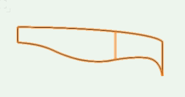
Hello I am new to vectorworks, look thru lots of tutorial and my brain is burning. I need help to construct a simple curve with arch line (see attached) what do should I use? thank you for your help. Kalo
-
Hi. Would you mind posting a link showing some samples of your work, please?
-
Hello. Looks like an interesting project. Please let me know if you still need help with it. My website is https://newland.works/. Please check out Recent Projects to see some of my recent work. I use many of the advanced features in Vectorworks: plug-in objects, hybrid symbols, worksheets, scripts, graphic legends, digital terrain modeling, and renderworks. My contact info is on the Bio & Resume page. Best of luck with your projects!
-

AI Visualizations-Thougthful discussions
Jeff Prince replied to Luis M Ruiz's topic in AI Visualizer
Isn't it interesting that the majority of the conversation here is about the "How do I get the tool to do _____ " instead of the philosophical questions @Luis M Ruiz posed? That gives you a window into the answer to this AI debate.... Creativity won't be democratized, rather the imitation of creativity will be commoditized... ...and the consumer won't care. Why should they when most of our fellow professionals just want to use this stuff to make up for their own inability to create? Architecture is headed the way of Graphic Design and will largely be a race to the bottom based on price and building codes. Only the wealthy and powerful will be patrons of true artistic pursuits. Maybe some of us will find opportunity as garden hermits on the estates we once designed. Craftsmanship and the trades are already dying a slow and undignified death, unless you can make a YouTube channel showing someone making trinkets. And while the uniformed will point to Etsy and the 'rebirth' of farmer's markets as examples to the contrary, the reality is most of that stuff is just drop shipped by Alibaba of delivered to the artisanal cheesemaker's house by Sysco. Social media is destroying communication. The world is once again generally swinging towards authoritarianism. It feels like the people are becoming increasingly self absorbed and trading the 'greater good' for 'greed is good' once again. Maybe AI can work on those things too and become our ambivalent overlord. More likely it will proclaim "you are bugs" and act accordingly. That's why AI is so good at producing dystopian images, it's preparing us for the spiritual and physical eventuality of the human race. I'm for one am not going out like Kent Brockman. Too heavy? Here's what the AI Visualizer produced with the following prompt: Creativity will be commoditized by AI It's interesting how AI images can sometimes remind me of Omni magazine covers from back in the day. It's gotta be tough being a sci-fi artist right about now. and then... "when the AI creativity party ends with unicorns and Flying Saucers" and finally.... Creativity Factory And people thought Brave New World was scary... what happens when AI is minding the hatchery?


-
 yoshifumiwada changed their profile photo
 - Yesterday
-
Heliodon not casting shadows because of dark theme?
Jeff Prince replied to Vilardaga's question in Troubleshooting
The Attributes Panel and/or Class settings can effect a heliodon object. If you place the heliodon on a Class that is set to Solid color fill and use at creation, you will see the effect. Also, if your attribute panel's fill is set to solid and you have a color other than white selected, you will see this effect. It's been this way for as long as I can remember and likely the source of your problem.- 1 reply
-
- 1
-

-
An alternative to the animation tool
Jeff Prince replied to Cadplan Architecture's question in Wishlist - Feature and Content Requests
@Josh Loy it would be handy if Vectorworks could use Saved Views as keyframes for an animation instead of having to draw a path for a camera to follow. I imagine most of us find it pretty easy to set up a handful of key views compared to drawing animation paths. Here is a rudimentary example I just made using saved views. It would so much smoother if Vectorworks could switch between the views without changes in acceleration or pauses for clicks, yet sometimes these qualities are helpful when presenting and discussing a model (the acceleration and stopping when departing/arriving at a view). keyframing.mov -
I needed to add a custom bit of truss to my company's library, in order to get the new symbol to play nicely with the rest of them I had to remove the cross section UID from 21 objects in order to make the system work in any configuration. I understand the reasoning for locking the factory symbols to a cross section but this is a major effort work around. Please consider adding a way to streamline the process or provide the resources for 48 hour turn around on VW created objects.
-
 Seth Moak joined the community
 -
1st Angle vs 3rd Angle projection...
Jeff Prince replied to digitalcarbon's topic in General Discussion
Because different cultures have different ways of looking at the world and developed ways of communicating this. As long as it is standardized and known, most people do not have difficulty with these concepts. If you try to force your ways onto situations designed for something else, you will have difficulty... like reading Arabic or Chinese and applying English conventions 🙂 Is this the esoteric answer you seek? -
 That results in 96 Depth (vertical boards) = 2 I can't think of anything that is 96x2 in the fence... the posts are set at 96" intervals - but are 4x1.62 in profile.
 -
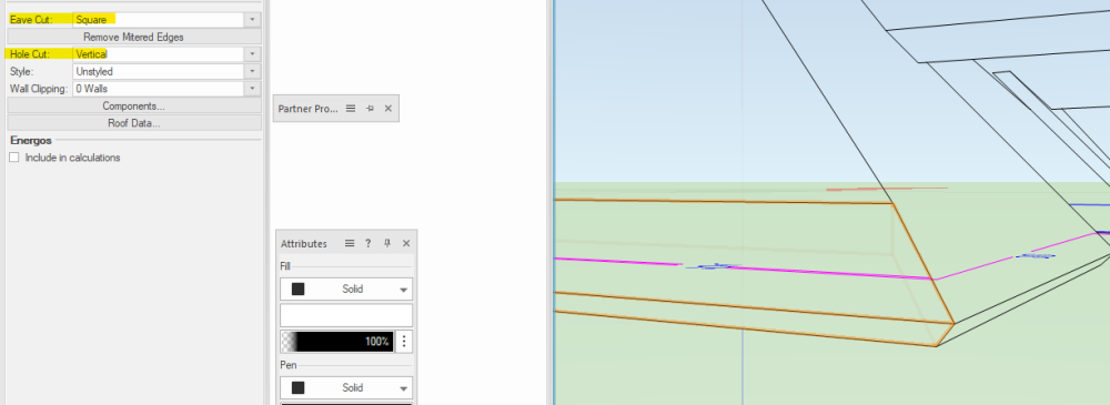
working fine here, make sure only eave is selected as square cut, leave hole as vertical:
-

1st Angle vs 3rd Angle projection...
digitalcarbon replied to digitalcarbon's topic in General Discussion
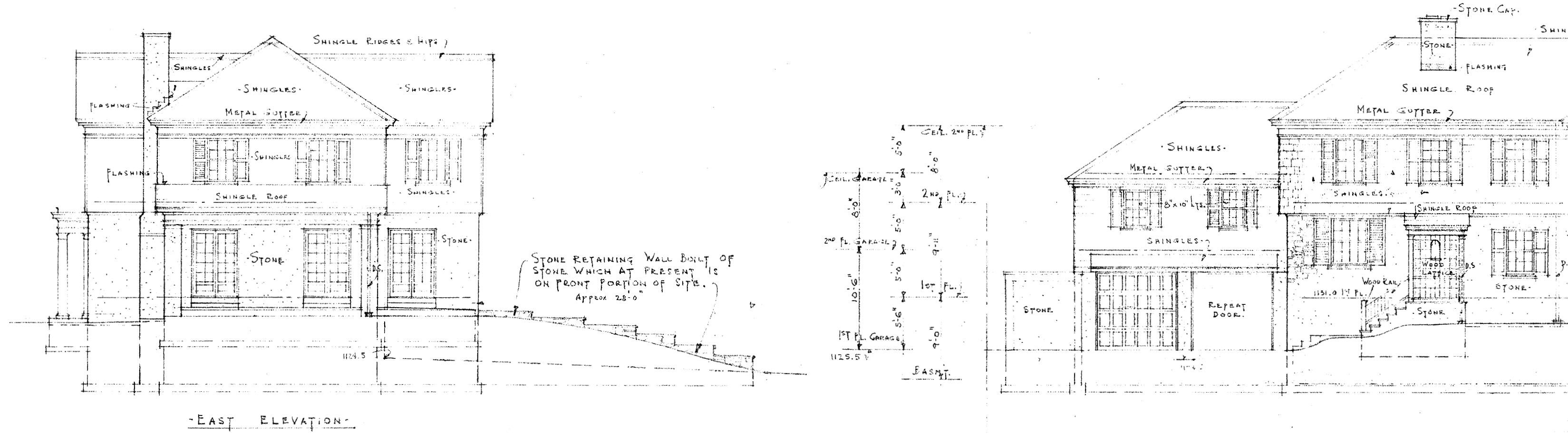
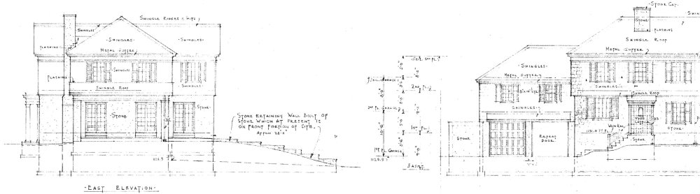
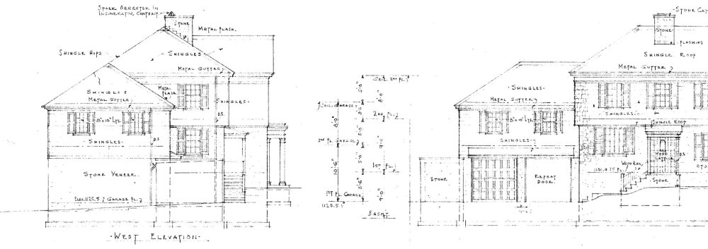
I have the feeling that for big things a human walks around to the right and left so that is the way they draw. People mentally "walk" to the corner of the bldg on the paper and there is the elevation only a few inches away. One would not take their eyes that are focused on a bldg corner and move them to the other side of the paper looking for the adjoining elevation. The key word is "adjoining". But for hand held objects they can flip back and for without moving their body. I cannot believe someone sat down in history and after finishing a front elevation (see above) they then decided to place the right side of a building on the left of the paper (as show in one example above) and then showed friends and family who all said "yea, brilliant! I get it." Hence, without another rational explanation...and seeing that it needs to be rational (I hope it is) I will assume that it has to do with size of object in relation to the human body & what we hope to find when we take mental walks through our drawings. -
1st Angle vs 3rd Angle projection...
digitalcarbon replied to digitalcarbon's topic in General Discussion
-
1st Angle vs 3rd Angle projection...
digitalcarbon replied to digitalcarbon's topic in General Discussion
I would draw the left elevation to the left of the front elevation as they have a shared corner In architecture one would show all elevations. -
 Hello Vectorworks Community, I'm currently working on a project that involves updating all Panel Layout objects using the "Update From Schematic" command. This command is accessible through the Object Info Palette, but I haven't found a way to automate it via VectorScript. My Goal: I need a script that will iterate over all Panel Layout objects in my drawing and run the "Update From Schematic" command on each one. This is essential for synchronizing the panel names and connector tags based on their connected sockets. What I've Tried: Iterating over objects and using SetRField and ResetObject to force an update, which didn't achieve the desired result. Searching through the Vectorworks Function Reference for any related functions or commands, without success. Challenges: The "Update From Schematic" command isn't available as a menu command, and I haven't found a corresponding VectorScript function. Directly forcing a refresh or toggling properties does not update the panel names and connector tags correctly. Questions: Is there a hidden or undocumented method to programmatically invoke the "Update From Schematic" command for Panel Layout objects? Has anyone found a workaround or script that successfully updates these objects in bulk? Would using Python scripting in Vectorworks provide more options or flexibility for this task? Any insights, examples, or suggestions would be greatly appreciated! Thank you in advance for your help! Andy
 -

1st Angle vs 3rd Angle projection...
BartHays replied to digitalcarbon's topic in General Discussion
I think the answer is tracing paper?? Wouldn't you have the same question about guide lines for 3rd angle if the chimney were on the other side of the house? But more to your point, putting the "right" on the "left" seems pretty unintuitive. I'm guessing that before the days of digital drafting, it was easier to imagine a viewer on the right side and an object and an opaque plane on the left so the "projection" of the right side ended up on the left. Again, guessing, that in the later days of CAD it became much more common to imagine a transparent plane between the viewer and the object, like a window. And, it makes more sense to most of us that the right view goes on the right. But in the end, it is all about how we train our brains to visualize 3D. -
I'm not familiar with using shared dimensions like that. In your example, unless there was uncertainty the heights could be omitted in the side view.