
digitalcarbon
-
Posts
2,172 -
Joined
-
Last visited
9 Followers


.thumb.jpeg.48a6fdc44e48c98b8e1b507e86e57e95.jpeg)

Recent Profile Visitors
9,557 profile views


-
Ref Design Layer Missing completely
digitalcarbon replied to digitalcarbon's topic in General Discussion
@shorter I just rebuilt it. I still cannot find out how it went missing. -
Ref Design Layer Missing completely
digitalcarbon replied to digitalcarbon's topic in General Discussion

-
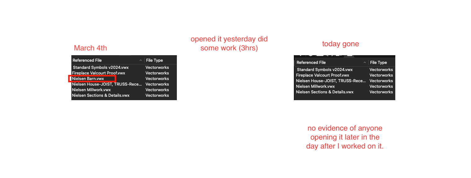
So I have a file I worked on yesterday (VW2024 8). It has a file "barn" referenced into it. I have about a dozen layers with Referenced DLVPs showing the "barn" floors, etc. Today the entire reference is gone & naturally DLVPs don't even exist. I have never had this happen before. This is not a case of changing layer names in the "barn" file then needing to update the DLVPs so they show. I do that all the time. It's really hard to just delete a ref as it asks if you want to keep anything. I know I did not do that. Has anyone ever had this happen?
-
Yearly versions need to go
digitalcarbon replied to digitalcarbon's question in Wishlist - Feature and Content Requests

-
Sorry about the deleted videos. They have been moved to a new location.
-
done in VW
-
@BartH ok I did. (I have SuperGrok by the way)

-
@BartH that was slick.
-
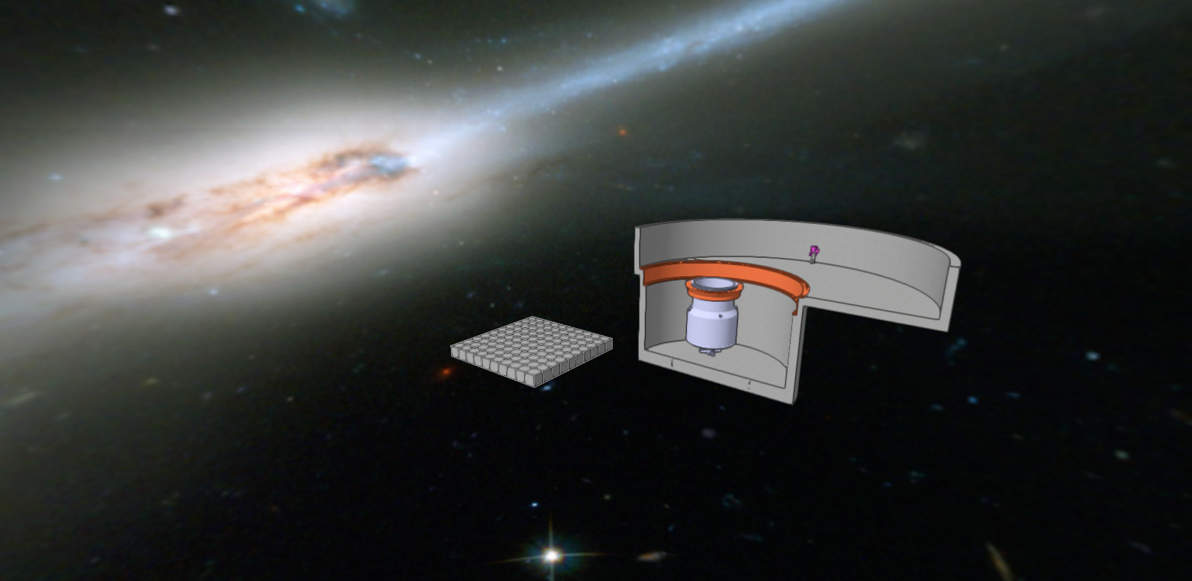
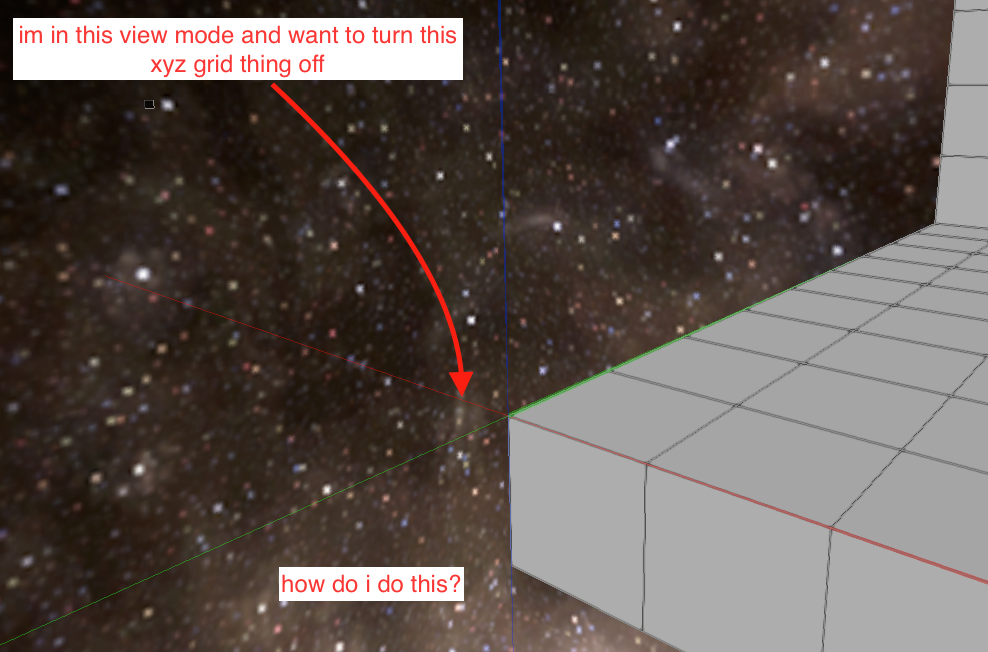
On a side note. Anyone have better space background, one that is less fuzzy?
-
VW used for video content.
-
@Tom W. Ugh. so simple...I looked all over for that. Thanks
-
-
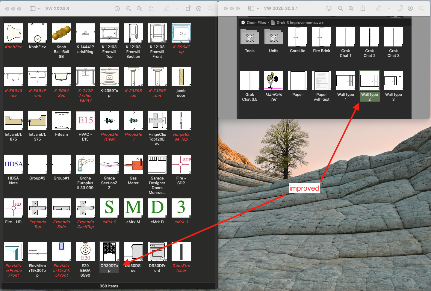
it also came up with a new composition of an existing material which improved the performance of that material. Hours of research all done in a few min. all work is shown in longhand. so one can review how it came to the conclusion and "check" its work.
-
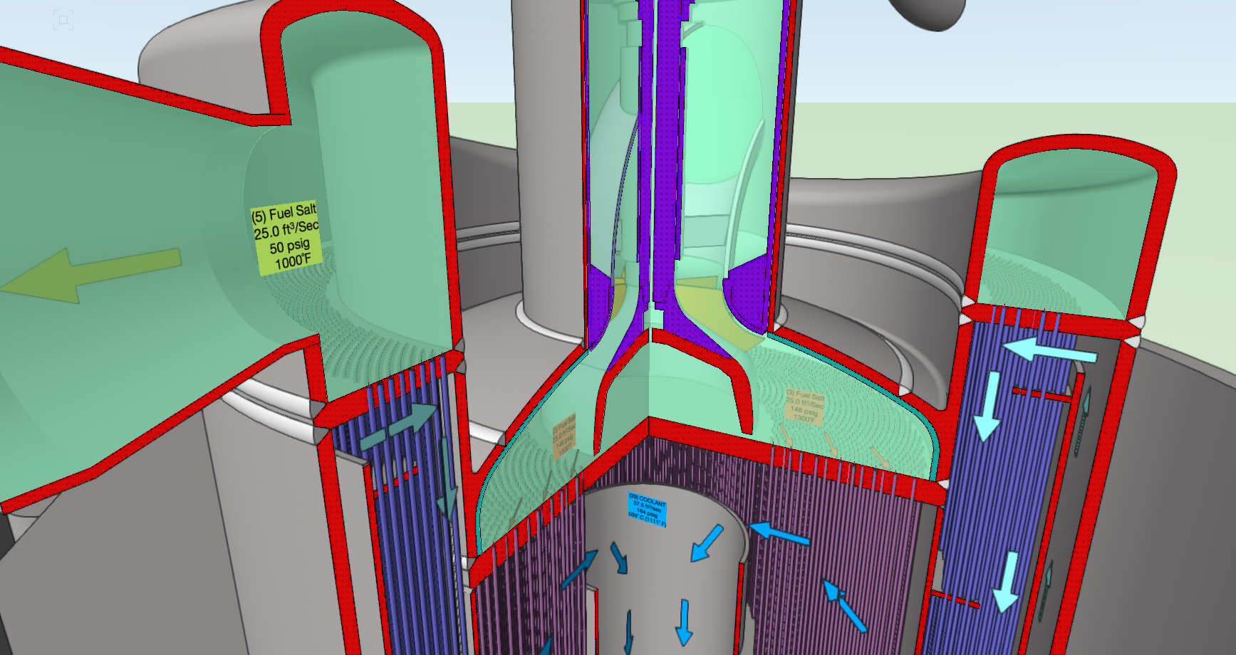
me - this is the laundry. I laid out the items the client has requested. I also added in a few more items. What is your opinion as to the layout and function? Can you make any recommendations? Grok - (ok, its not there yet) I just had an interesting conversation with it over the past few days regarding a specific wall type for a special furnace. While it cannot draw a detail, it did work out all the thermals and made suggestions to materials. it even got into the maintenance of the furnace lining.
-
I don't want to spend anymore time needing to read how to do stuff, fix stuff, find stuff, submit stuff.