bcd
-
Posts
3,600 -
Joined
-
Last visited
2 Followers

Recent Profile Visitors
9,137 profile views


-
Place the GL on a multi-page Sheet
-
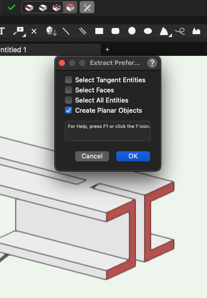
Enhancing the tool for custom start & end bearing is a good idea. In the meantime you can Extract the profiles and extrude them rather than trying to trace over them. You can also push-pull the bearing to the correct length but this will convert the Framing Member to a Generic Solid losing it's other functionality.
-
Have you checked for Lighting Pipe Symbols that may be lurking in the RM?
-
Why not just import that into VW from C4D?
-
Far Out Object Warning
bcd replied to Pat Stanford's question in Wishlist - Feature and Content Requests
YES! And even an AutoMove Objects option would be great, one that would also adjust Viewport Crops & positions & annotations so that everything looks as it was but now closer to the Internal Origin -
'North' is just towards the top of your screen ±45°. It could just as easily be called 'roughly towards the top of the screen" The Labels applied to the interior elevation marker are easily editable in the OIP and the resulting SL Section VPs will auto-coordinate with these. The SLSVP Drawing Titles are also customizable.
-
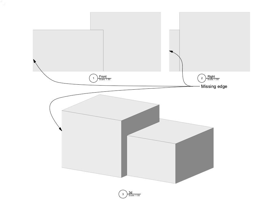
Yes but I was talking about VPs where there is no Crop object. However, I'm wrong in my assumption that it is new in VW2025. It is also the case in VW2024 I just hadn't noticed it until testing VW2025 over the weekend.
-
In VW2025 uncropped SLVPs have no margin, resulting in missing edges.
-
3D Modelling: Working Planes and Creating Simple 3D Objects
bcd replied to Michael Siggers's topic in General Discussion
-
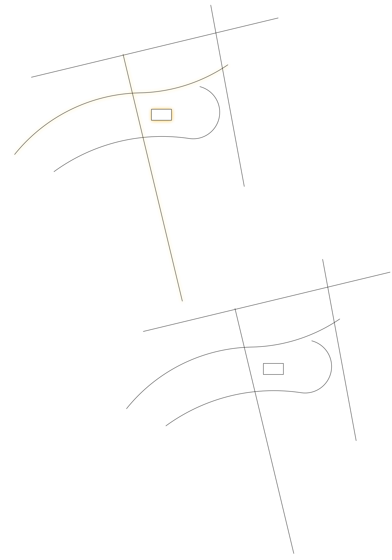
Clever ways to highlight a line using data visualisation?
bcd replied to line-weight's topic in General Discussion
Maybe Drop Shadows. It's subtle.
-
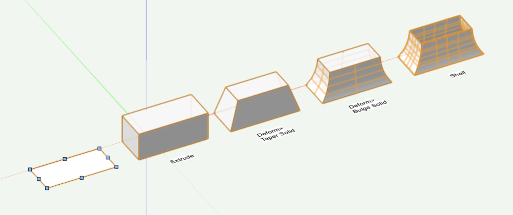
Best Way to Model Joinery With Moulding/Routed Profiles
bcd replied to blaaj's topic in Architecture
Sometimes for those level of details you need to model them directly after you've created your cabinets. It's a good idea to place them in a class of their own so you can turn them off in Top/Plan views if desired. (The new -in VW 2025 by object visibility functionality will most likely make this last obsolete)- 1 reply
-
- 2
-

-
Increase your Hidden Line Rendering settings' Crease Angle to eg. 35°
-
Another alternative is to place a 3d locus at the center point of each end of your members. Run a Worksheet to collect the co-ordinates of those. Export to Excel or some such and number the nodes and members. eg - point 1, point 2 Member 1 point 2, point 3 Member 2 that together with the cross sectional shape should be enough for the engineer to run his calcs.
-
If it's very complex writing a Marionette script to draw a 2point Nurbs curve from ctr of start face to ctr of end face for each extrude would be worthwhile. I suspect manually drawing them will be faster & more controllable. You might also place 3d loci at the end of the Nurbs curves You could even number them sequentially to make it easier on the other side.
-
Yowzah!!! Gone are the superfluous Groups with special visibility classes Gone are the unnecessary creation of Symbols so they can live on their own Layer for fabrication drawings. Gone is repetitive Grouping and Editing Ungrouping of objects just to study a single subset of objects without the congestion of the rest of the drawing. etc. very nice (ps I'm digging the wallpaper inside that cabinet, very specific)