KingChaos
-
Posts
262 -
Joined
-
Last visited
2 Followers

-
is anyone here who can help me get the txt textures on my Lidar scan?
-
hi, i failed with the textures. it imports the geometry as well, but its white and somehow the textures (usdz???) is not imported into vw23
-
it will take pages ^^ if i start now for all functions. okay, i see it will take some time. for the first, i want to have for each segment a red symbol placed (3D-cabinet of Extragroups Interiorcad) and a popup for each segment where i can select a symbol which is placed. 🙂
-
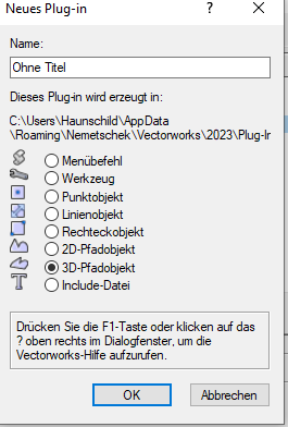
@MullinRJ can you pls help with the minimal code is needed for a 3d pathobject? The height ob the object will be the length between the 2 clicks i guess?
-
@DomC haste meine PN bekommen?
-
Hi there, has someone experience with this? I need this for making the black symbols (with interiorcad 3D-cabinets and or or interior 3D-parts) unique. If they are in a black symbol and i place it more then 1 time in my workspace there will be collusions with the databaserecords when i "symbol to group" them. So i might need this "DoMenuTextByName" somehow to make them individual. BR KingChaos VS:DoMenuTextByName - Vectorworks Developer
-
2024-01-23 06-10-53.mp4 ah ok, my english is not best but i think i got it now. Can you tell me some hints for the "3D-Pfadobject", this is what i need for a very cool tool. I want to let the user sketch a polyline (only lines no arcs) and behind this a sales counter/cabniets will appear in seperate modules (in red symbols). Then we can apply cabinets on the whole wall with 1 polyline for purchaseinformation about the chipboards and fittings in a few seconds and for rendering if u need a fast cheating-fassade of cabinets just to make some renderpics for the customer. Like you see here i do it with topsolid (mov1). i made it with a marionette with a control geometry. But its not working 100% until the extragroup will implement dowels and screws in the backwall of the cabinet. 99 % of all carpenters use "medium-density fiberboardAE" with notches as a backwall. But Store construction cabinets use allways 19 mm chipboards witch u cant nutch. When i apply some dowels and screws outside the cabinet container of interiorcad the symbol will turn blue and the parametric is lost. I THINK THAT, Only if all the the cabinetparts 100 % intern jointed/connencted i will have a red symbol and can modify the databaseentries (length, width and height). But this wont take more then 1 upgrade then 2024 i think it could be realised in 2025. I want to be ready if this will come. in the videos u see, that is a polyline, and i can apply some cabinets behind it. If i change the poly, all cabinets are following. This works not so bad a i described, but only with cabintets without dowels and screws. the marionette was not so complicated but has some oddities too. Each cabinetsymbol must be different (in the ress. manager), because of the naming of the cabinets and cabinet parts. Therefore computerworks gave me this hint, to use the command. VS:DoMenuTextByName - Vectorworks Developer It should start the "namingprocess" which automatically ran, if u copy a cabinet with strg+mouse1. Else i have several 3DParts vom Interiorcad with the same name and then the databaseconnection is lost on all except one part. In VWX my "path extrude" projects looks like this, 3 years passed since then 2024-01-23 06-45-42.mp4 (mov 2). Now i have some capacity to put it on a new lvl, why not with 3D-Path-Extrude Plugin? br KC
-
yeah this is how my marionette for metal parts works. except the miterdatabaserecord all is working properly. i made Solid for the drillings (cylinders and or cones) and for the endmiter and subtract them. to reduce the number of nodes i sketched each cross section with a 2D geometry and use this to extrude and subtract. But now i want a new approach. @ Jesse: i USED this point object, only the icon was of tool 🙂 now i ask myself, wether a path extrude works like the wall plugin from vwx. i could use it later for my masterplan. can u specify what difference i from point to rectangle and what malus (oddities) u spoke about? QRX V11_clean.vwx
-
the marionette i made (500 nodes) compiled 20 min to object and was very bad. this is faster with 150 nodes but its to slow. so i made it slimmer but it took several minutes to update, after i modified the xg cabinet, where i used it as a box object. the problem is, that marionette does a spaghetticode, useless lines of code each node so this is not the way i can use.
-
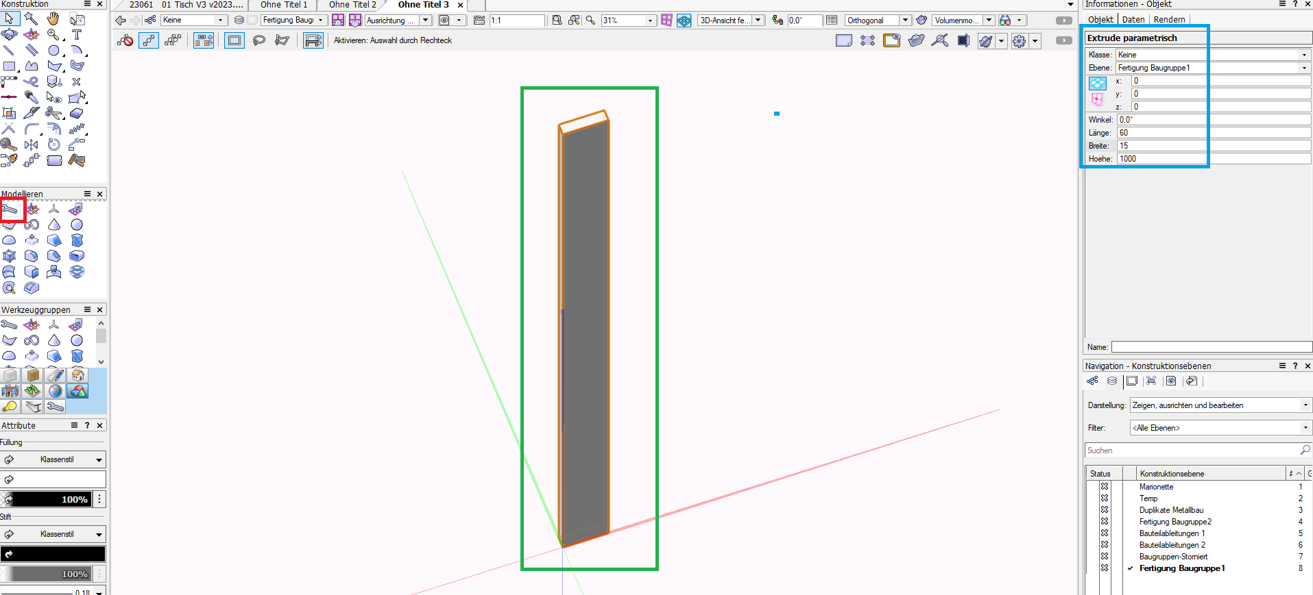
hey, ok i ran the tool and it works. Now i need to know, how i can make a symbol out of it with OIP parameter ports. After this i will try to hollow the extrude.

-
ok, i tried now to make an extrude and hollow it. i cant find this "hollowed extrude" in the script ^^
-
-
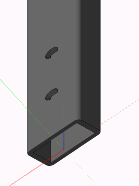
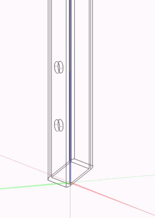
i think it would be possible to hollow, drill and cut objects ^^ with script to make somethin like this: And later i think it will be possible to make presets (styles) of parametersets?
-
ok i think i can make it. But, how to make a red symbol out of it to use it in my xtragroup cabinet as a "box object"?
-
not at this time, but i think i will make it. before i used topsolid and there is not a single line, square or circle without any callable parameter in the topsolid. so there is nothing complicated scripting needed like here. All stuff is assoziative and follow IN REAL TIME all modifications u make. So as i started VWX i was only able to cry about this "dead geometry " 😛