All Activity
- Past hour
-

draw an polygon spaced across a 2D path object
Jayme McColgan replied to Jayme McColgan's topic in Python Scripting
sorry y'all been awhile. sometimes I gotta do my day job. lol for those in the future looking for an example here's what I ended up going with. hPath = vs.GetCustomObjectPath(objectHand) arrows = int(vs.GetRField(PIO_handle, recname, "arrows")) amount = arrows + 1 testing = vs.HPerim(hPath) / amount starting = 0 for i in range(amount - 1): starting += testing vs.RegularPolygon(0, 0, 30, 3, 1) last = vs.LNewObj() cur_loc = vs.PointAlongPoly(pathHandle, starting) vs.HRotate(last, 0, 0, vs.Vec2Ang(cur_loc[2])-90) vs.HMove(last,cur_loc[1][0], cur_loc[1][1]) -
There was a book, "Custom Solutions in Vectorworks 8.5" which did a good job of explaining all this. Unfortunately I can't find an electronic version. 😞 Here is a very quick summary from my memory: Point, Linear, Rectangle, 2D Path, and 3D Path, are all object types and just have different number of clicked to define and number of control points. Point (1) and Linear (2) are pretty simple. Rectangle gives you two points on the center line, and then one point that is offset from the center line at 90°. I haven't used the two Path options so I can't remember what they have. Tool is for scripts that are not going to create a new object or objects that need to collect a lot of data in order to draw the object correctly. The Objects in the previous paragraph actually create the own "tool" so they can be added to the workspace. Command creates a Menu Command that runs without requiring clicks in the drawing. If you need 2 or 3 points to define you object, then using a Linear or Rectangle mode might be worth considering. HTH
-
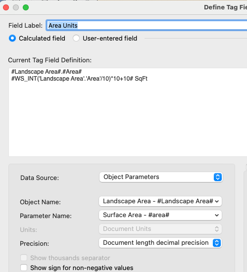
That's a good point. Presumably 'area' just gives you the 2D area whereas 'landscape area.area' gives you the 3D surface area... which may or may not be an issue depending on the circumstances
-
 Henrik Quaß joined the community
 - Today
-
Nurbs vs Polygon Area in VW Worksheer different? or not?
Pat Stanford replied to matteoluigi's question in Troubleshooting
The NO values in the D column are being counted as 1 in the VW version. Change your formula to put the NO or blank in a separate column and it will total correctly. Or manually subtract NO from the total- 1 reply
-
- 1
-

-
I think you are displaying the 'Landscape Area'.'Area' from the first part and the formula in the WS_ is incorrect. Try: #WS_Int('Landscape Area'.'Area'/10)*10+10# SqFt Which is very close to @Tom W.'s suggestion. For trouble shooting, include both lines in the Data Tag Definition to make sure you are getting what you want. This is what I used in testing. Each line in the Tag Define Tag Field dialog box will display as a separate line in the tag. Start simple and work toward the eventual goal.
-
I don't know what it was, but editing the Graphical Legend Style and changing the scale from 250 to 1:1 seems to have fixed the problem for me. Let me expand on that. The above is what I tried that forced a recalculation of the GL. I then went back to the original version of the file and just did a Recalculate on the GL without editing the style and it also seems to have cleared the problem. Tested in VW2024 Update 4. I don't have a way to test in VW2020. If 2020 is not the version you are running, please update you signature so we can more easily help.
-
import vs import math import Marionette @Marionette.NodeDefinition class Params(metaclass=Marionette.OrderedClass): # Erscheinungsbild # Name this = Marionette.Node("Get Point on Poly and Distance") this.SetDescription('Gibt einen Punkt an der angegebenen Entfernung entlang des Polygons zurück, beginnend vom ersten Eckpunkt des Polygons, und berechnet die Entfernung zwischen zwei Punkten') # Eingabeanschlüsse poly = Marionette.PortIn(vs.Handle(0), 'hPoly') poly.SetDescription("Das Eingabepolygon") nDist = Marionette.PortIn(0, 'nDist') nDist.SetDescription("Die angegebene Entfernung") p1 = Marionette.PortIn((0, 0), 'p1') p1.SetDescription("Ein 2D-Punkt, der den Startpunkt repräsentiert") nSehne = Marionette.PortIn(0, 'nSehne') nSehne.SetDescription("Eine angegebene Länge, die den Radius eines Kreises repräsentiert") # OIP-Steuerungen tolerance = Marionette.OIPControl('Toleranz', Marionette.WidgetType.Text, '0.0000000000001') tolerance.SetDescription("Ein akzeptabler Unterschied zwischen den berechneten und approximierten Werten") # Ausgabeanschlüsse p2 = Marionette.PortOut('p2') p2.SetDescription("Der Ergebnispunkt") vTan = Marionette.PortOut('vTan') vTan.SetDescription("Der Vektor tangential zum Polygon am Ergebnispunkt") b = Marionette.PortOut('b') b.SetDescription("True, wenn der Knoten seine Aufgabe erfolgreich abschließt, sonst False") # VERHALTEN def RunNode(self): # Eingaben poly = self.Params.poly.value dist = self.Params.nDist.value tolerance = self.Params.tolerance.value p1 = self.Params.p1.value nSehne = self.Params.nSehne.value # Skript result = vs.PointAlongPolyN(poly, dist, tolerance) p2 = result[1] vTan = result[2] # Berechnen der Entfernung zwischen p1 und p2 c = Marionette.TupleMap(lambda x, y: (y - x) ** 2, p1, p2) l = math.sqrt(sum(c)) # Annäherung in noch kleineren Schritten und Präzisierung in noch kleineren Schritten while l < nSehne: new_dist = dist + 0.000001 # Annäherung in noch kleineren Schritten if new_dist >= nSehne: # Überprüfe, ob die neue Entfernung nSehne überschreiten würde break else: # Präzisierung in noch kleineren Schritten step = 0.00000001 while dist < new_dist: dist += step result = vs.PointAlongPolyN(poly, dist, tolerance) p2 = result[1] vTan = result[2] c = Marionette.TupleMap(lambda x, y: (y - x) ** 2, p1, p2) l = math.sqrt(sum(c)) # Ausgaben self.Params.b.value = result[0] # Koordinaten mit höherer Genauigkeit erfassen self.Params.p2.value = (round(result[1][0], 15), round(result[1][1], 15)) self.Params.vTan.value = result[2]
-
The chord is now calculated from p1. However, processing the list would also have to use a sequence of consecutive points. How do I have to incorporate this into the code? import vs import math import Marionette @Marionette.NodeDefinition class Params(metaclass=Marionette.OrderedClass): # APPEARANCE # Name this = Marionette.Node("Get Point on Poly and Distance") this.SetDescription('Returns a point at the specified distance along the poly starting from the first vertex of the poly, and calculates the distance between two points') # Input Ports poly = Marionette.PortIn(vs.Handle(0), 'hPoly') poly.SetDescription("The input poly") nDist = Marionette.PortIn(0, 'nDist') nDist.SetDescription("The specified distance") p1 = Marionette.PortIn((0, 0), 'p1') p1.SetDescription("A 2D point representing the start point") nSehne = Marionette.PortIn(0, 'nSehne') nSehne.SetDescription("A specified length representing the radius of a circle") # OIP Controls tolerance = Marionette.OIPControl('Tolerance', Marionette.WidgetType.Text, '0.0000001') tolerance.SetDescription("An acceptable difference between the calculated and approximate values") # Output Ports p2 = Marionette.PortOut('p2') p2.SetDescription("The result point") vTan = Marionette.PortOut('vTan') vTan.SetDescription("The vector tangent to the poly at the result point") b = Marionette.PortOut('b') b.SetDescription("True if the node completes its job successfully, false otherwise") # BEHAVIOR def RunNode(self): # inputs poly = self.Params.poly.value dist = self.Params.nDist.value tolerance = self.Params.tolerance.value p1 = self.Params.p1.value nSehne = self.Params.nSehne.value # script result = vs.PointAlongPolyN(poly, dist, tolerance) p2 = result[1] vTan = result[2] # Calculate distance between p1 and p2 c = Marionette.TupleMap(lambda x, y: (y - x) ** 2, p1, p2) l = math.sqrt(sum(c)) # If the distance between p1 and p2 is greater than or equal to nSehne, extend the distance until it reaches nSehne while l < nSehne: dist += 1 # Increase dist by 1 unit result = vs.PointAlongPolyN(poly, dist, tolerance) p2 = result[1] vTan = result[2] c = Marionette.TupleMap(lambda x, y: (y - x) ** 2, p1, p2) l = math.sqrt(sum(c)) # outputs self.Params.b.value = result[0] self.Params.p2.value = result[1] self.Params.vTan.value = result[2]
-
I don't have a way to test in VW2012, so all my tests are in VW2024. Worksheets have been greatly enhanced since 2012 so it is likely that things for you are different. A lot of your problems stem from trying to have different objects types work in a single database in the worksheet For Column G, you can't specify an extra criteria to the Volume function. The criteria passed to the function is the criteria that is used for the database. So change the formula to just =Volume() and you will get your value for each object, not just the extrudes For the Length, the Channel - 3D objects don't respond to the Length function properly, for that you have to use the 'Channel - 3D'.'Length" field value. You can put both versions in a single column using an IF function. =IF(OBJECTTYPENAME='Channel - 3D', 'Channel - 3D'.Length, LENGTH) If you end up using more object types, then you could use nested IFs, but it can get complicated pretty quickly. Another option would be to use separate databases for the different object types. Each would use the proper functions for the object type. Hide the database header row and they would all look like a single table, but you would not be able to "interleave" them in a sort. To change to Rack Parts, you would need to right click on the database header row and Edit Criteria and change to the Rack Parts Record is Present. You would also need to change the formula in column A to show 'Rack Pars'.'Name" instead of Box Parts. HTH
-
And you might want to update your signature. Your still says VW 2019. My Signature has the steps.
-
 Dominique Corpataux changed their profile photo
 -

'Wall Styles' to reflect real-world construction
Kevin C replied to Amorphous - Julian's question in Wishlist - Feature and Content Requests
Matt, I think that VW as a company is missing the point of the question that was raised. Over the years VW has struggled with providing real time working solutions to shortcomings in the actual software. If you go back to the start of this thread and look at @Jonathan Pickup's post, this is all that we are really asking for. You mention closures and visibility of components in Top/Plan - this is still touch and go as far as working properly in the current version of VW (2024 v4.1) - how many years was this in the making and it was released not working properly, actually damaging VW files and entire projects in the process - almost as badly as the catastrophe of the introduction of the Title Block Manager. One might ask, if I am so disappointed with VW, why don't I go elsewhere. The simple answer, I like the software - but there is only so far that that will travel. It's a question I seem to be asking myself more often. I have invested many thousands of pounds in this software and all the seats that I own, my business would seriously struggle if I were to change software providers. Although if I did I would be able to access manufacturer libraries much easier and also collaborate with other design team members without any concerns or compatibility issues. Something VW needs to take note of, especially as they broke their promise of never changing to a subscription model - the users never wanted or asked for this. -

macOS 14.4 Compatibility Issues with Vectorworks
Tom Macie commented on JuanP's article in Tech Bulletins
Yes! Same here. Don’t keep them open together. -
This keeps cropping up - I just happened to put a roadmap request on this item earlier today. I'll summarise below - Is what I'm suggesting too radical, or is it just basics. The ability to create a wall containing all the necessary components required to construct the wall up to and including say the outside cavity. Being able to 'stick' a cladding (of our choice) on to the structure - with the ability to control both vertical and horizontal extents), but when doing so the cladding recognises openings like doors and windows. A great number of 'cladding' variations happen at locations the designer has chosen specifically to create a specific outcome, sometimes we just want to experiment to see how the design will look with different elevational treatments before deciding on the final options. These don't always tie-in with a predetermined formula. This is technically achievable at the moment by excluding the external cladding material from the wall structure and placing a 'cladding' wall directly in front of the main wall, but then all openings etc. have to be manually added in - and it gets very messy. One advantage though is that wall joining and component joining becomes much better, as we are in control where walls join together and not a piece of software
-
 LcAstF joined the community
 -
Hey there! Ever tried installing Vectorworks 2024 Update 4.1 in silent mode? I've run into a problem: the command doesn't seem to pass the session automatically. attempted: using the command " .\Vectorworks 2024 Installer.exe" --unattendedmodeui none --mode unattended --Serial "XXXX-XXXX-XXXX-XXXX-XXXX" --LDFChoice licenceID. However, despite my efforts, the session didn't progress automatically as expected. Any idea what the problem might be?
-
Pat, Will take a look. Thank you.
-
 I'm sometimes digging in old cases and I have found Yours @RBergman Could You please show us some updates how did You job worked?
 -
Irrigation - Turn Off Automatic Irrigation Network Update
Piotr Karczewski replied to samgbickel's topic in Site Design
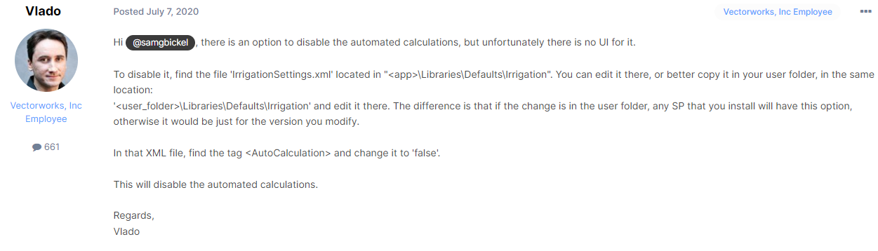
I'll leave it here for users how are still running VW 20xx-2022 this is the way to solve and turn off auto calculation in irrigation by @Vlado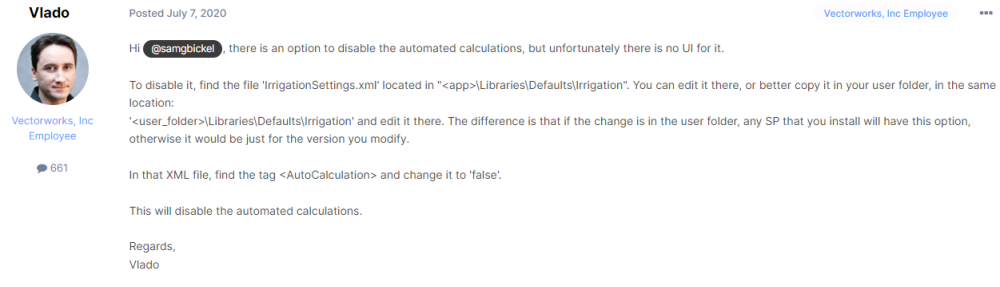
-
Suspend Irrigation Network Update
Piotr Karczewski replied to Dave Phelps's question in Wishlist - Feature and Content Requests
@Dave Phelps and/or others who are still running VW 20xx-2022 the way to solve and turn off auto calculation in irrigation by @Vlado:
-
Good point it should be possible to make it. I'll try to make some test when I will have free time...
-
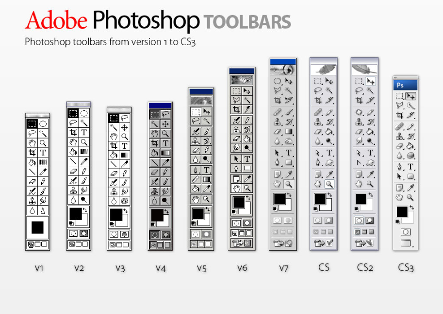
No comment: Source: https://www.deviantart.com/lukeroberts/ My favourites: I do not think, that icon changes are bad but in some cases they are not recognizable from the first site. The best is split tool evolution from scalpel to paintbrush, also small arrows which expresses movement they made sense...
-
Agreed. If you want a faithful representation of such a building + are not looking to add/remove/modify the geometry then this is the way to go, and an approach I've taken on one particular project. My experience is that if you are going to be combining existing + proposed architecture in the same model, adding/removing/modifying walls/doors/windows/floors/roofs + looking to produce separate 'as existing' + 'proposed' drawings, then it's preferable to do it all using Wall/Slab/Roof objects. I personally would not be modelling the existing architecture using 3D Solids unless I had a very good reason for doing so which in my case has only been one project so far. Remember, existing architecture is often just as complex as the new elements + involves multiple components: presumably you wouldn't advocate modelling these build-ups manually? Plus what about tagging + reporting on those objects? Analysing existing + proposed thermal performance etc? What about Top/Plan representation of the different objects? My point is that it's misleading + inaccurate to simply say 'solids are far better for existing conditions' but I think you've qualified that statement now + we're probably kind of in agreement, just coming at it from different positions/workflows.
-
I don't believe you can. You have more control over this kind of thing using Data Tags however. I assume you're talking about the built-in Plant Tag.
- 1 reply
-
- 1
-
-
 Hi Pat, sorry for the late answer. Here's a file created with VW2012 - that worksheets behave different than in the office.. Unfortunately neither column F nor J calculates correct - legacy issue? ok - here we go Column I lists the weight of steel. Column J shall calculate the volume of the several parts Column G shall calculate the weight of every part - and summarize in row 2 Column H, K and L - please ignore (just tests). Experienced to have the Length of the parts in different column (for 3D-channel and Extrudes) I have another column with IF((H2=0),J2,H2) to have all length values in a common column. There are more columns to calculate other things - so it's a bit more content at the end. So let's say I created the Box-worksheet working correctly - is it possible just to copy this worksheet, make some settings (where and how...) - in order to calculate the values of the parts in class "Rack" - in opposite to create the Rack-worksheet again from scratch? Inbetween I did it from scratch but keep curious if this can be done a 'smarter' way, y'know? Thanks, Peter test.vwx
 -
Is there a way to have a plant tag display on two lines? I have a tag that is a bit long and would fit better on two than one.
-
Depends on the subject matter...and how high you set your bar, I suppose, and what you consider acceptable as a base to coordinate your work against and what quality of drawing you want from the model. 15th century cottage with no vertical walls, and with huge deflection in floors and joists = 3D model. If the existing building is 'virtually' vertical and horizontal, I might consider walls and slabs but it is not necessary other than for expedience. An existing wall does not change, unless it is demolished, or rebuilt, or clad or lined, in which case the new bit is a 'wall object'. Existing bit does not need to be. It can remain a solid. There is less risk of it being modified inadvertently when a wall object updates.