


zoomer
-
Posts
8,886 -
Joined
-
Last visited


-
That is good news. I saw the video of latest D5 release and it looks great. I always thought it would be just a Rendere like VRAY or Corona. But realized now that is a complete real time render solution like Twinmotion, Enscape, Lumion, ..... And it supports Blender ! (But so far have not looked how deep that support or exchange will go in reality) Unfortunately I also realized that D5 is Windows only !? Bummer.
-
In VW, Image Props, to follow the Camera, will rotate around Z axis only. (Which usually makes sense for cut out people or plants, even for slight bird eye views) In 3D Apps like e.g. Cinema4D they can rotate about all axes by default. (In C4D I had to lock mine to Z axis only manually for my purposes) So an image prop may not the best solution for your purpose. An option would be a 3D mesh globe with earth texture applied that you may find on google warehouse or somewhere else, in a 3D format that VW can import.
-
That was my manual measuring experience so far too. I always hoped Lidar Scans would prevent this.
-
Not sure if really everything was colored .... but I once had to learn that a Heliodon sun color will adapt to the color of the Class the Heliodon is assigned. (When Attributes assigned by Class) I tend to assign bright Class Colors to non-architectural objects like cameras or lights, which I never use anywhere else. Pink and purple in my case. And suddenly all my renderings were pink and it took me a few days to realize the cause.
-
How to draw (lines or walls) parallel to another on the fly?
zoomer replied to MarCur's topic in General Discussion
"T" key is the official general VW drawing support for your problem and the main intention of the "T" key. As I mostly have to deal with 90° perpendicular/rectilinear Walls only, I usually just misuse the "T" key to lock only to only a single X, Y or Z axis. Which was the only way to do so, until we got the 3D Giszmo, now even available for standard Selection/Drag Tool. But in VW there are often workarounds. Often by using Tools other than intended ... Or in this case, if I want to draw a Wall in the same arbitrary angle like another Wall .... I would just copy the initial Wall to the new point and adapt its dimensions, change its Wall Style if necessary or whatever needed - before I try to find the recommended way ... -
I assume a GPU or GPU driver issue ? I only tried to scan more than one room at a time with Room Plan Mode and was disappointed. I do not understand why it lost the angle. All Walls should have been perpendicular but Room Plan was about 15° off. I think Nomad needs more artificial or better human intelligence. This is all great @michaelk That was new to me. It does. But I do not get where Nomad takes the angle from. It is neither true north angle nor did I find any possibility to control this in any way, like starting perpendicular to a Wall. I already tried to mimic that manually but did not find any benefit. I assume negative floor height level comes from iPhone to Floor distance (?) Looks like you made a secret from the most important 6. point ......
-
AFAIR there was an option to "embed" DWG References when importing in advanced settings (?) Not sure if it is always the best solution to bring all references into the import file.
-
Ah, yes. But for me it is always important to be able to assign extra buttons App specific for all 3D and CAD Apps. So I usually need the driver suite bloatware. It is easy if for standard Apps like browsing, mail and such. I could even use the magic mouse for this comfortably. But as soon as drawing on screen, I would need bettertouchtool for extra cursor speed without acceleration. And still never reached a satisfying MMB or "scroll wheel" click. (I really admire all Mac CAD and VW users staying with their magic mice)
-
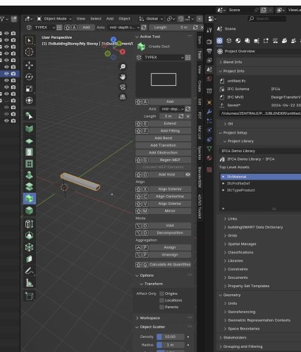
You can play with Blender and BlenderBIM AddOn, it's free. They lately started adding (basic) 3D Duct Tools to BlenderBIM. Have not yet played with it. Potential workflow for a VW user : - Export VW Building geometry by FBX - Import in Blender - save IFC Project from BlenderBIM - create Ducts -> import Ducts to VW by importing the IFC
-
Short update, I never got my delivery because alternating any of my USB C adapters was not available. From time to time I got new availability/delivery updates by email. At one point in March or April I accidentally clicked on the "cancel order" button instead of the link to my order .... there was no way back and my money was send back .... So no MX and I forgot about Mice because my 3DCon CADMouse currently clicks reliable again for now. (Might have been a special humidity and temperature window that made clicks fail) But I still would go with a MX after your feedback. I was just again warned about Logitech's monster driver from many sides. As I need to keep the other monster drivers, (Wacom for my Cintiq and 3DCon for my Enterprise/Navigator) I am not that amused to need a 3rd one from Logitech.
-
Mac OS Sonoma 14.4.1 makes VW2024 unusable
zoomer replied to astephens's question in Troubleshooting
I had that once for VW and Bricscad too. But that was with 14.4.0. and not seen it in 14.4.1 again so far. I use a M1 Mini desktop with a single Monitor. On a Macbook with multi monitor setup or clamshell mode it may be more likely to experience such problems. For Macbooks, for similar issues, it was recommended to just close and reopen the lid. When I lost my VW Menu, I realized that there is still the Apple and VW main entry on the left. And when I clicked on the VW Menu, my whole VW Menu came back .... -
The Gizmo only appears in 1st and 4th Mode. When you switch to 2nd or 3rd Mode, there is no Gizmo. In the Video you switched through all Modes already, but you Selected in Mode 1 and 4 only, the ones with Gizmo visible .... Why it does appear in 1st Mode at all - no own knows ...
-
Maybe the Server is just down ? Recently again, from time to time I have large lags to access this Forum from Germany. Maybe more of VW Servers or even the AI Server or EU to US routings are overloaded ? BTW The AI works also well with german prompts.
-
For Foundations I also use 60 cm wide Walls. I think some also use Slabs but I think connected Walls and assigning individual Wall Styles is the most flexible way for later changes and adaptions. And you can individually overwrite heights.
-
Or maybe we will have an AI App that watches all that AI generated content for us.

