HebHeb
-
Posts
86 -
Joined
-
Last visited
-
How does one edit the centerline of a path site modifier?
HebHeb replied to hollister design Studio's topic in Site Design
i came to the conclusion that it is faster to redraw the whole modifier when "big" changes are needed. wich is a real pity... could be the best and most useable modifier ever for me, but for now I stick with the "old" modifiers (and my Marionette Objects that do kind of similar things...) just because of the poor changeability options. But I am curious to read how other people work with this tool! -
huge file size (300 mb is not) can be caused by many resource manager objects another hint may be: many instances of the MO inside the file? try using "styles" for your network/ object
-
same bug for me (since a few months?) I just deleted everything I didn't needed inside the node (for example: I just needed volume) then it worked fine 🙂
-
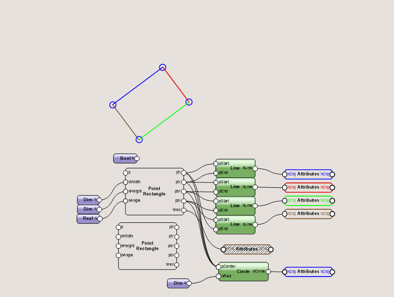
when operating with nurbs curves (my go to when creating solids inside marionette) some things to mind: - for closed curves take the first point and use it at last point also (otherwise they are not "closed") - use the "loft surface" node to generate solids (get familiar with the settings (rule, solid, close, ...) - chek the order of the curves and their point direction (with the data flow nodes everything is possible)
-
In DomC's Node Collection is something that might be interesting? Actually there a a few Nodes/ small example Networks that might help u with your idea! DomC Nodes - Marionette - Nodes - Vectorworks Community Board
-
Thanks for reaching out! @Letti R was so kind to help me out with a alternative Python script ❤️ this did exactly what i wanted. @Antonio Landsberger But thanks for the version 2 of this node!!! I am 100% sure I will use it later in another script.

-
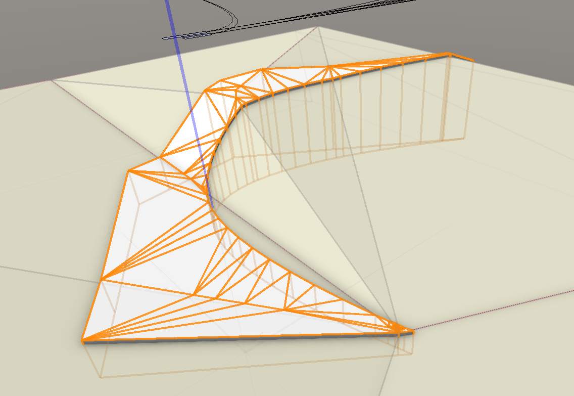
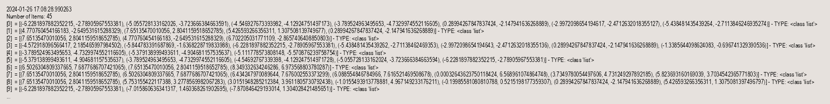
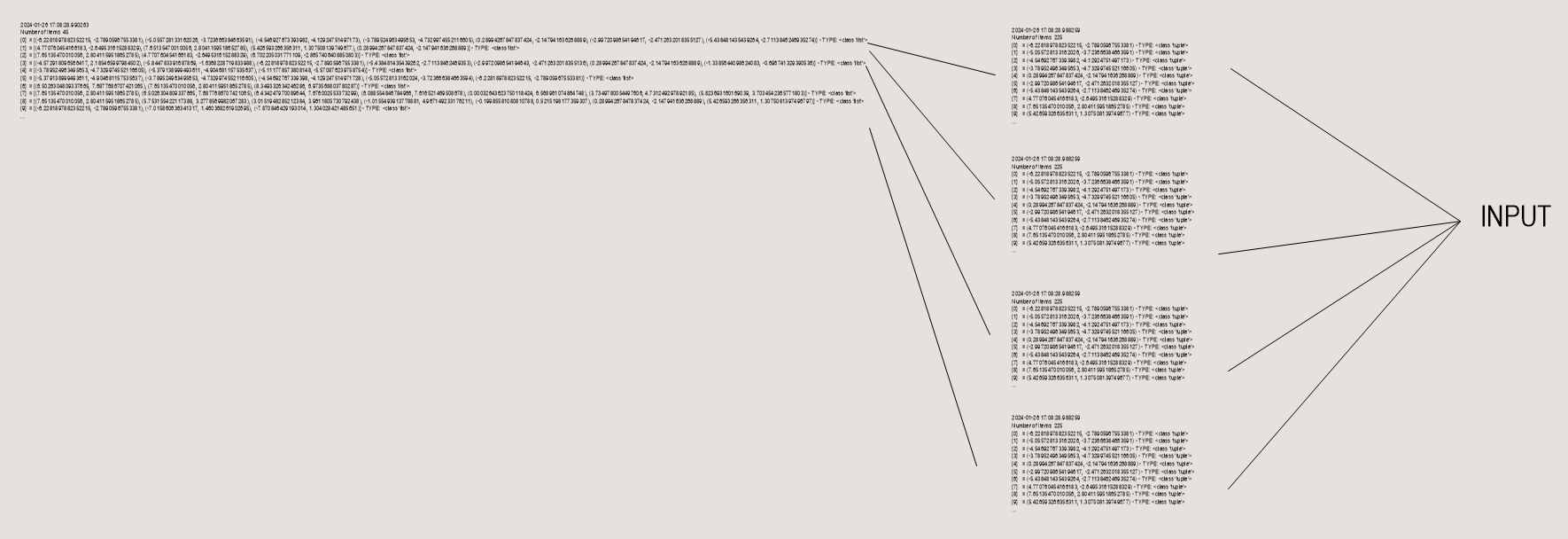
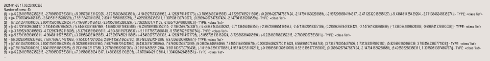
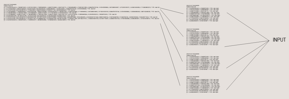
i guess this is something basic, but never did this with marionette: i have a list of points that looks something like this (points for each poly) i want to triangulate each poly separately and not the whole polys together... so i need a flattened list for each 'list' and not the whole list flattened. can anyone help me? thanks!
-
Notches at regular intervals in a curved ceiling
HebHeb replied to Tobias Heinzmann's topic in Marionette
I think there not enough Info to help you. But one Node comes to my Mind that might be wort lookin at: "Get Point On Poly" so you can place and rotate Objects along Polyline shapes.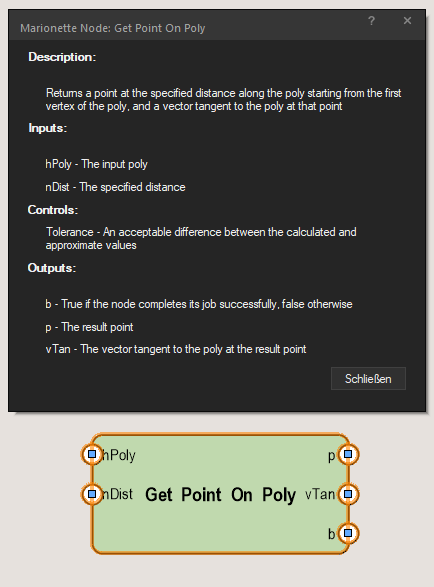
-
1. not very complex, some nested math... squences, ranges, series,... recalculating z-height of polys etc... graphically: no 2. of course only the dedicated gpu active As said: just curious if maybe more "generel problem" acoss other hardware configurations. Might have a chance to test on a system with dedicated gpu only next week...
-
Hey there, i have some Networks/ and or Marionette Objects that crash my Windows 2024 Update 3 Installation of Vectorworks, on MacOS everything just works fine and as expected. I have already sent a test file to my local Distributor and they said that the issue was now reported to Vectorworks Inc. I also experience much faster response of Marionette on MacOS than on Windows... even my "slow" M1 with 16GB RAM (13" Pro late2020) is oddly faster than my i9-12900H, 64G RAM, RTX 3060 (Laptop GPU) Windows Machine. Wouldn’t expect such huge differences with that hardware. So out of curiosity: Anyone else in this community having similar trouble?
-
Question on DomC's "Extrude along Path with Ref point" Network
HebHeb replied to HebHeb's topic in Marionette
@DomC @Pat Stanford this works perfect! 😍 in this context: is there any acess to the "fixed direction of the profile"? i would literally die for a english Version (or at least the possibility to switch from german to english) Sometimes it is really hard to guess the english terms and get proper search results...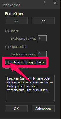
-
Question on DomC's "Extrude along Path with Ref point" Network
HebHeb replied to HebHeb's topic in Marionette
Thank u! I will test it tomorrow and will report my results here 🙂 -
Question on DomC's "Extrude along Path with Ref point" Network
HebHeb replied to HebHeb's topic in Marionette
ty Pat for reaching out! ...and thats exactly the problem: no matter how the profile is moved, after an operation the movement is reset 🙂 if not operated on the result its working, thats exactly what DomC's solution is doing. -
Question on DomC's "Extrude along Path with Ref point" Network
HebHeb replied to HebHeb's topic in Marionette
had some time to work on this again... Whenever I operate on the resulting "VW-Handletype: 86 Plug-in object" (in this case convert to 3d polys > mesh) the movement of the profile is lost (happens with any operation (also bool) unfortnetly there is no info for 3D Path Plug-in Object (86) on the developer page that might help me to sort it out myself... @DomCHave you any idea how I cloud avoid this behavior? Extrude along Path with Ref point (3D Path Plug-in Object - Handle Type 86).vwx -
I can't remember excatly; but could it be possible that this only happes with active plan rotation?