
DomC
-
Posts
625 -
Joined
-
Last visited
1024.thumb.jpg.1dfb7f260e9069ac2ad50c243b95956d.jpg)


Recent Profile Visitors
16,144 profile views


-

How to assign a texture to a 3D object (Solved)
DomC replied to Carles Olle's topic in Python Scripting
was not able to wait and solved it with a funktion: def get_longest_direction(final_contour): # Define the contour points # Calculate the centroid (center) of the contour centroid_x = sum(point[0] for point in final_contour) / len(final_contour) centroid_y = sum(point[1] for point in final_contour) / len(final_contour) # Initialize variables to keep track of the longest edge and its direction max_distance = 0 direction = '' longest_edge_points = () # Iterate over the points to calculate x and y distances between consecutive points for i in range(len(final_contour)): # Get the current point and the next point in the list (wrapping around at the end) x1, y1 = final_contour[i] x2, y2 = final_contour[(i + 1) % len(final_contour)] # Calculate the x and y distances x_distance = abs(x2 - x1) y_distance = abs(y2 - y1) # Check if x distance is the longest so far if x_distance > max_distance: max_distance = x_distance direction = 'x' longest_edge_points = ((x1, y1), (x2, y2)) # Check if y distance is the longest so far if y_distance > max_distance: max_distance = y_distance direction = 'y' longest_edge_points = ((x1, y1), (x2, y2)) # Determine the position of the longest edge relative to the centroid (x1, y1), (x2, y2) = longest_edge_points # Check the relative position of the longest edge if direction == 'x': if centroid_y > y1: # Edge is below the centroid position = 'below' else: # Edge is above the centroid position = 'above' elif direction == 'y': if centroid_x > x1: # Edge is to the left of the centroid position = 'left' else: # Edge is to the right of the centroid position = 'right' return position longest_direction = get_longest_direction(final_contour) '''and for the mapping this code''' vs.SetDefaultTexMapN(rec, 3, 0) vs.SetTextureRefN(rec, texRef, 0, 0) # flip horizontal #vs.SetObjectVariableInt(rec, 540,1) vs.SetTexMapBoolN(rec, 3, 0, 7, False) vs.SetTexMapBoolN(rec, 3, 0, 5, False) #texture part, overall is 3. Selector: init:1, flip:2, repH:3, repV:4, long edge:5, worldZ:6, auto align:7 angle = 0 if 'links' in c: if longest_direction == 'left': angle = -90 * (pi / 180) if longest_direction == 'right': angle = 90 * (pi / 180) elif longest_direction == 'above': angle = 180 * (pi / 180) if 'rechts' in c: vs.SetTexMapBoolN(rec, 3, 0, 2, True) if longest_direction == 'left': angle = -90 * (pi / 180) if longest_direction == 'right': angle = 90 * (pi / 180) elif longest_direction == 'above': angle = 180 * (pi / 180) vs.SetTexMapRealN(rec, 3, 0, 4, angle) -
How to assign a texture to a 3D object (Solved)
DomC replied to Carles Olle's topic in Python Scripting
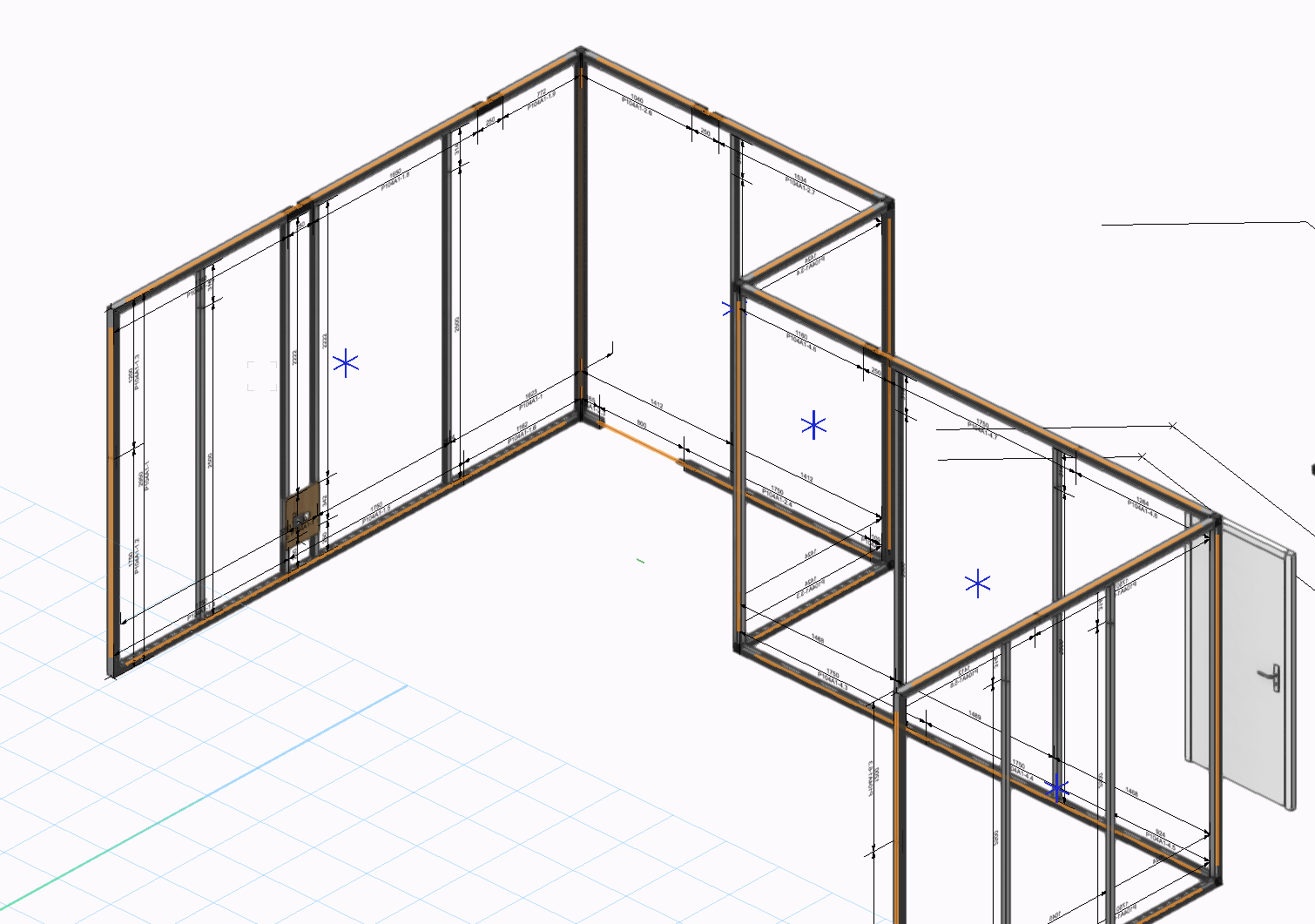
Hi Searched the Forum but did not found another thread about the textur mapping: 1. I have attach a textur on an extrude. The Extruse can have 4 or more vertex points of a 2D Poly 2. Starting point is alsways the same and also the direction is known. Main question is, how to prevent texture mapping from aligning to the longes vertex of the face? I use as example this, to rotate, which works. Also Flipping is working vs.SetTexMapRealN(rec, 3, 0, 4, angle) I tried this but this does not change the mapping vs.SetTexMapBoolN(rec, 3, 0, 7, False) vs.SetTexMapBoolN(rec, 3, 0, 5, False) What i do now is, i get the bound in x and y (view on the face) and then rotate by 90 degrees if the y is bigger than y so texture would stay horizontal aligned to the world coordinates , which works for rectangular shapes. I now have to deside if i analyse the shape (if shape is not rectangular) for the longest edge or if there would be an existing function for that. My testing code looks like this: vs.SetDefaultTexMapN(rec, 3, 0) vs.SetTextureRefN(rec, texRef, 0, 0) # flip horizontal #vs.SetObjectVariableInt(rec, 540,1) vs.SetTexMapBoolN(rec, 3, 0, 7, False) vs.SetTexMapBoolN(rec, 3, 0, 5, False) #texture part, overall is 3. Selector: init:1, flip:2, repH:3, repV:4, long edge:5, worldZ:6, auto align:7 angle = 0 ''' if 'links' in c: if breite < h: angle = 90 * (pi / 180) else: if len(final_contour) < 5: #Rechteck angle = 180 * (pi / 180) else: angle = 180 * (pi / 180) ''' if 'rechts' in c: vs.SetTexMapBoolN(rec, 3, 0, 2, True)#flip vertical axes '''texture is aligning not to the bounds it aligns to single edges of object''' if breite < h: angle = 90 * (pi / 180) else: if len(final_contour) < 5: #Rechteck #vs.AlrtDialog(tex_name) angle = 180 * (pi / 180) else: #vs.AlrtDialog(tex_name) angle = 0 vs.SetTexMapRealN(rec, 3, 0, 4, angle) #vs.SetTexMapBoolN (rec,3,0,3,True) #vs.SetTexMapBoolN(rec, 3, 0, 2, False)#flip vertical axes #vs.SetTexMapBoolN(rec, 3, 0, 2, True)#flip horiz axes res = vs.SetEntityMatrix(rec, (ps[0], ps[1], 0), 90,0,b) vs.SetClass(rec, c) Short movie which shows, that the texture changes alignment if another edge is getting the longest edge. Auto-Texture-Align.mp4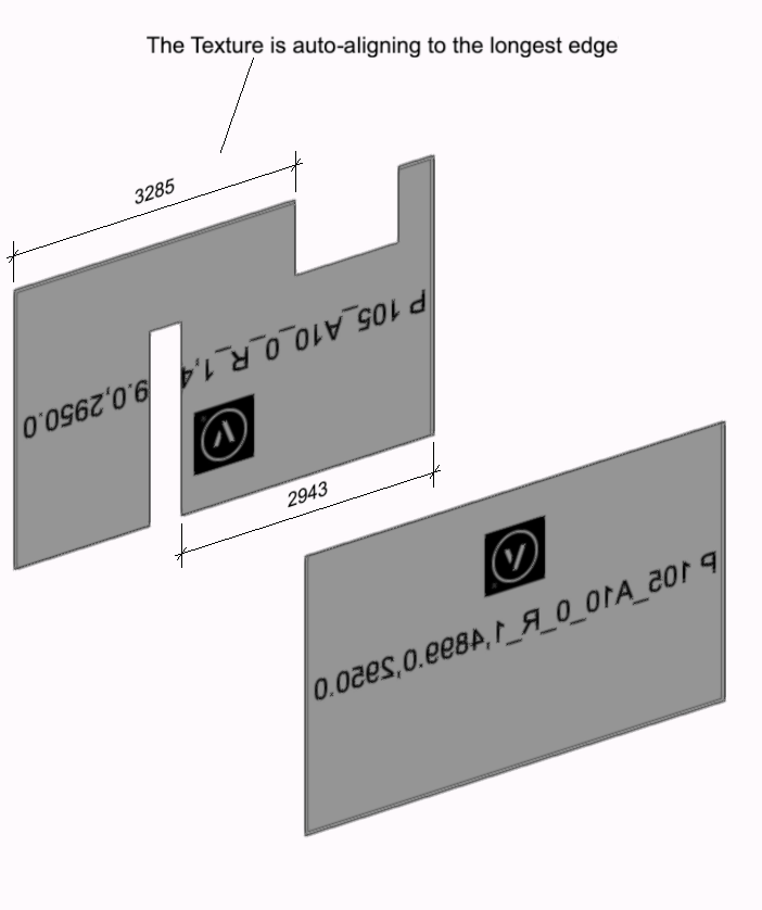
-
 Yes it should be possible. If you edit the script you find the string input for the feald name of the area Since 2024 it is a new field (MeasuredNetAreaNum) you can see the right field names with a worksheet as example. In past i did used other fields but i think i never used the grossArea (BruttoFläche) Field. The Field MeasuredNetAreaNum is a special Field which is compatible with Vectorscript and has not to be parsed from a string to a number which created so many troubles in past version (while the biggest time consume of the script was the game, how to convert a Text like "1.045,186m2" (which can be different for every document settings, and country settings of the computer) in a number like 1045.2?) Just to say, why i recommend to use one of the field with ... Num at the End. This can be converted to a Number in a reliable way by the custom Marionette Node Str2Num from the Wohnungsstempel Marionette.
 -
Hi Create Additional (dynamic or non dynamic Field) in the Tag: 1. Edit Record Format and create new field 2. Edit Symbol and link new Textfield to that new Record Field 3. Edit the Script and link an input or a computed value to that record field Exit the Script Style and then you should have a new input Field. Importand. Edit the right Symbol, which you use in the Wohungsstempel.
-
Create a texture resource from image in a folder
DomC replied to jonasfehr's topic in Python Scripting
I'm as happy as a little child right now! I just made a short movie to show what I can use this for. It allows practically a real-time exchange of wall textures, which can be accessed from a shared location or via web API. The customer can see their printable areas directly with a pre-prepared image file, and I can visualize his demands in real-time. REAL-TIME-VISUALISATION :-))) import image texture.mp4 -
Create a texture resource from image in a folder
DomC replied to jonasfehr's topic in Python Scripting
After again i have to use an import for textures. I searched the script reference and found this one: def vs.SetTextureSize(texture, newSize): return None I would say it does exactly what we searched for. size in inch. So if we want the texture should have 1000mm in real world we use newSize = 1000 / 25.4 -
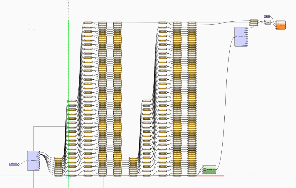
I analyzed that several times with many Networks from users. The more nodes the slower. Do not know, if it depends of "unpurged and many lines" or on the fact, that every node has a geometry representation, Circles and polylines for graphical representation and generating the script. My workflow for PIOs for professional usage is, to have just a few nodes. And one node contains the PIOs main-code. This can be 1000 or 3000 lines. if i export this as a python file it has 1326 lines. The PIO needs 2 seconds to execute. If i export this 500 nodes, it has 29000 lines. Those are just pass nodes. Execution Time of this PIO is 0.07 seconds. So executing 10 times (290'000 lines of code) is not even a second execution of the first example with 1300 lines, needs about 2seconds depending on the size and number of linkes objects etc. Just to show, there is not direct relation between number of lines and speed. I also think about optimizing. But if we say, one should optimize the network, so we have 10times less lines. It would be the development investment on the wrong side maybe. It would sound maybe for the world to say we reduces size of script 10 or 20 times. But is is the wrong priority to focus improvements on the number of created code-lines by marionette. It maybe could result in longer waiting time for your example, because the intelligents to create the code maybe needs then more time. Just want we think clever about where someone would invest developing time. We have maybe the same wishes and should not judge about the right solution. At the End, the wish speed by copy or import objects on the file. And we want security that a deleted node or wrecked graphical network does not change the script. I think the direction of improvement should be, to be able to dump/cache the finished script in a text-based form (one node, one resource, one stile etc.) So your 1500 nodes don't need to be part of your pio anymore. Nodes are good to easy build the script or easy edit update it. Thats why we love graphical scripting. But to use the PIOs in our models in a fast and 100% reliable way, nodes are not needed. Also i am pretty sure, those are producing your speed issue not the number of coded lines.

-
It is a copy of the node content in that path and the node run without it and user get not messages about that link. At the time you edit the node code also nothing happens if the resource not exists, if the resource exists it will update if the resource is newer than the code inside the node. Only if you exit the node it will report, that the resource is not existing and it tries to create the path. And from this Moment you can edit the Text resource to edit the code. I think this is done, to be able to update the nodes and keep them synced. But a note will not update automatically. Because changing a node without control could break existing scripts. So it is a good think to keep nodes synced if needed or triggered manually. But if you developing a big code content of a node and need to run tests ever 30 seconds the workflow with a direct "import module" is better till the script reached a releasable state. The Import would throw an error a machine which is not linked to that path. So this is just a developing method. Then you go to the #COMMAND;REFFILE; method. Also there is the Method #COMMAND;READONLYREFFILE; with protect nodes from editing. And just read the file.This is how the standard-nodes are created. It is thinkable to download and install the module through the modul installer of Marionette or the Marionette own installer inside the node from Vectorworks Reprository or from a python wheel url. like we import pillow, numpy etc.
-
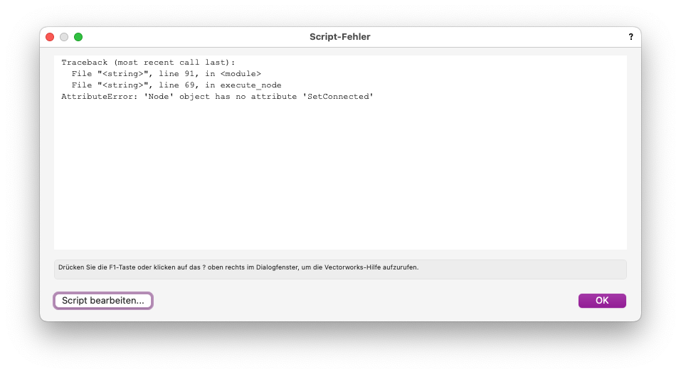
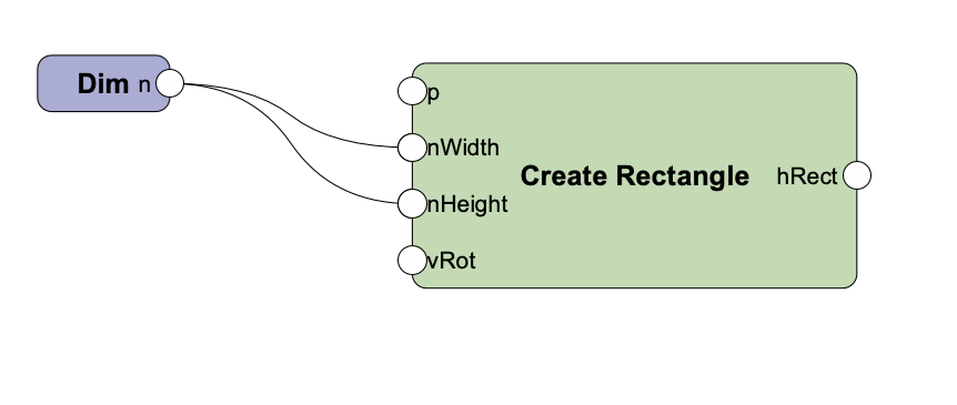
If you have luck a tool like ChatGPT can simplify your code or can help optimizing it. But we can not read take the output of those AI tools directly. Still someone have to verify the output or have to know what to do if there is still "a bug" 🐞 Lets make a spontan test. Marionette is drawing a rectangle. A very easy one. I export as a script: 160 Lines (cant post the code directly here) ChatGPT. I ask for making it more compact: Sounds good. Result 104 lines. But i do not except this is faster. Or even the first version is really measurable slow just because of the code BTW, that faild and the "optimized" script do not run, while the original script runs:
-
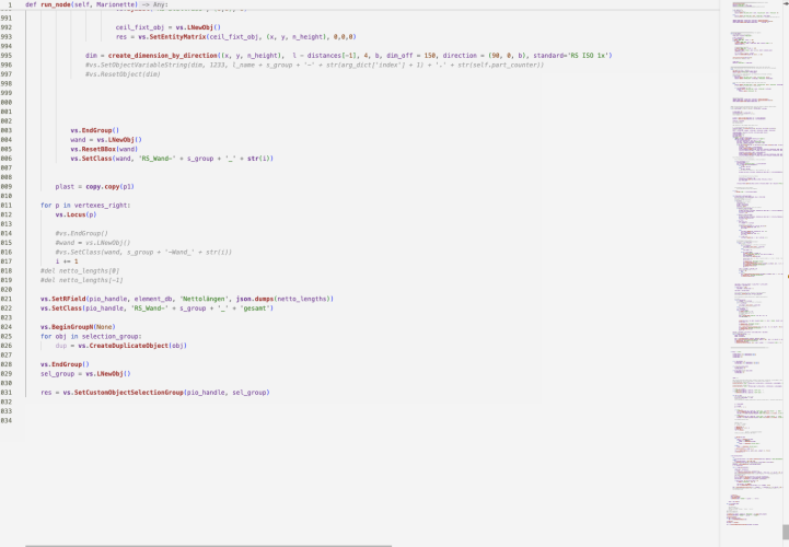
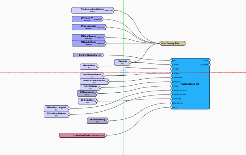
You can refer to a "text" resource, which is you node definition code like this at the Beginning of the node: #COMMAND;REFFILE;[UsrLib]/Defaults\Marionette\DomC\SystemWand_v13.py; @Marionette.NodeDefinition class Params(metaclass=Marionette.OrderedClass): The system detects if you edit last in Vectorworks via Node definition or via editor in the external file and will update. But it is not a direct link to an external module. But will work if it is disconnected to the external tool. The negative think about this, we (or i do not know) how to update the node without doubleclick and exit the node. So my beste Workflow to edit external code of a Marionette Node is as following: example: @Marionette.NodeDefinition class Params(metaclass=Marionette.OrderedClass): # APPEARANCE # Name this = Marionette.Node('SystemWand_v13') this.SetDescription("") # Input Ports objs = Marionette.PortIn(None) n_offset = Marionette.PortIn(0) n_height = Marionette.PortIn(3000) n_off_end = Marionette.PortIn(68) n_max_offset = Marionette.PortIn(750) profile_dim = Marionette.PortIn(30) s_group = Marionette.PortIn('') n_profile_max_horiz = Marionette.PortIn(2000) n_profile_max_vert = Marionette.PortIn(3000) n_strut_max = Marionette.PortIn(3000) b_Gehrung = Marionette.PortIn(True, 'Ecke Gehren') # 0 = Einlauf 90, 1 = Fallstrang 2x45 wire_in = Marionette.PortIn(False) # OIP Controls # Output Ports h_poly = Marionette.PortOut() p_vertices = Marionette.PortOut() # BEHAVIOR this.SetLinksObjects() # this.SetListAbsorb() def RunNode(self): import rs.systemwandv13 from imp import reload reload (rs.systemwandv13) rs.systemwandv13.run_node(self, Marionette) So i start normal and then i import my exernal code in the RunNode. Maybe it is also possible to import the complete node code but did not tried(needed) this yet. Important is to reload because of caching. This is a very good method for fast developing without refreshing nodes manually. And then the external module: def run_node(self, Marionette): # import modules from datetime import datetime import json import vs import math import copy from math import radians, sin, cos #from inspect import currentframe, getframeinfo #cf = currentframe() selection_group = [] error_log = [] # parent pio infos pio_handle = vs.Handle(Marionette.parametric_handle) pio_parent = vs.GetParent(pio_handle) pio_parent_type = vs.GetTypeN(pio_parent) #... here you can code everything you also can code inside the node. Hope that helps. Do not know what you want to do. I think the speed of Marionette not really depends of inefficient code. It is maybe the Number of nodes which makes it slower maybe by duplicate or copy/paste an Object. But maybe it is i am sure about this.
-
Aha, then you could use this one. I like this idea. Also for myself i have tons of scripts and this one can help execute them fast with a menu command and one single click. Thinkable ToDoes: - What would be cool, a palette with a searchable list browser or similar. I was never able to create propper popup with search bar - maybe support for sub-folders in module directory import os import importlib dialog_dict = {} def get_py_files(directory): # Traverse the directory tree and collect all .py files without their extensions py_files = [] for root, dirs, files in os.walk(directory): for file in files: if file.endswith(".py"): # Add the file name without the .py extension to the list py_files.append(os.path.splitext(file)[0]) return py_files def run_palette(directory=''): # Set the directory to search for Python scripts vs.PythonSetSearchPath(directory) # Set the search path for Python modules dialog_dict['res_names'] = get_py_files(directory) # Get all .py files id_dict = {} def dialog_main(): def CreateDialog(): # Create the main dialog layout dialog = vs.CreateLayout('Scripte Schnellzugriff', False, 'OK', 'Abbrechen') last_item_id = 10 act_item_id = last_item_id + 1 vs.CreateStaticText(dialog, act_item_id, 'Klicke auf die gewünschte \rFunktion.\r', -1) vs.SetFirstLayoutItem(dialog, act_item_id) # Create static text items for each script name for res_name in dialog_dict['res_names']: last_item_id = act_item_id act_item_id += 1 vs.CreateStaticText(dialog, act_item_id, res_name, -1) vs.SetItemClickable(dialog, act_item_id, True) vs.SetBelowItem(dialog, last_item_id, act_item_id, 0, 0) id_dict[str(act_item_id)] = res_name # Add a spacer at the end last_item_id = act_item_id act_item_id += 1 vs.CreateStaticText(dialog, act_item_id, ' ', -1) vs.SetBelowItem(dialog, last_item_id, act_item_id, 0, 0) return dialog def DialogHandler(item, data): if 10 < item < 10000: dialog_dict['func_id'] = str(item) return 1 dialog = CreateDialog() result = vs.RunLayoutDialogN(dialog, DialogHandler, False) == 1 return result result = dialog_main() if result: func_id = dialog_dict.get('func_id', False) func_name = id_dict[func_id] if func_id: # Dynamically import and execute the selected module module = importlib.import_module(func_name) directory_with_pytho_modules '/Volumes/SD_Card/Dropbox/Entwicklung/python_scripte' # Run the palette function to start the dialog run_palette(directory = directory_with_python_modules)
-
I always try to code and comment in in english (anyway the code is not good documented on this prototype script). However this is a good idea to access to the external resource and even not copy the script resource on the working document. The steps would be: 1. Read Workgroup folder in the Windows Registry or the Macintosh Application Support. Which can be done somewhere in this forum there is a workflow to read this path. 2. Adapt the script (The Starter Palette is just one column, if you have over hundred script it will fill up the screen, so this maybe has to by changed to dynamically create more columns if needed) 3. You could use the starter Script from my example. class vssmPaletteRunner(): dialog_dict = {} def run_palette(st_palette_name = 'ArgumentPalettenname', exclude_palettes=['ST Script Module'], res_path = ''): listID, numItems = vs.BuildResourceListN(49, res_path)#Symbols id_dict = {} dialog_dict = {} res_names = [] res_dict = {} for i in range(numItems): res_name = vs.GetNameFromResourceList(listID, i) if res_name != '': res_names.append(res_name) res_dict[res_name] = i dialog_dict['res_names'] = res_names def dialog_main(): def CreateDialog(): dialog = vs.CreateLayout( 'Scripte Schnellzugriff', False, 'OK', 'Abbrechen') last_item_id = 10 act_item_id = last_item_id + 1 vs.CreateStaticText( dialog, act_item_id, 'Klicke auf die gewünschte \rFunktion.\r', -1 ) #vs.SetStaticTextColorN( dialog, act_item_id, 2) vs.SetFirstLayoutItem( dialog, act_item_id ) for res_name in dialog_dict['res_names']: last_item_id = act_item_id act_item_id += 1 fill_number = 55 - len(res_name) fill_string = ' ' * fill_number #vs.AlrtDialog(str([last_item_id, act_item_id, res_name])) #vs.CreatePushButton( dialog, act_item_id, res_name + fill_string) #vs.CreatePushButton( dialog, act_item_id, ' ' * 50) vs.CreateStaticText(dialog, act_item_id, res_name, -1) vs.SetItemClickable(dialog, act_item_id, True) #vs.AlignItemEdge( dialog, act_item_id, 3, 1, 1 ) #vs.CreateStandardIconControl(dialog, act_item_id, 0) vs.SetBelowItem( dialog, last_item_id, act_item_id, 0, 0 ) if 'Elektro' in res_name: #res = vs.GetColorButton(dialog, act_item_id) vs.SetColorButton(dialog, act_item_id, 65000,0,0) #res = vs.GetColorButton(dialog, act_item_id) last_item_id = act_item_id id_dict[str(act_item_id)] = res_name last_item_id = act_item_id act_item_id += 1 vs.CreateStaticText(dialog, act_item_id, ' ', -1) vs.SetBelowItem( dialog, last_item_id, act_item_id, 0, 0 ) return dialog # Sample dialog handler # Uncomment this code if you want to display the dialog def DialogHandler(item, data): if item == 12255: #Enter Dialog for key in id_dict: id = int(key) vs.SetItemClickable(dialog, id, True) #vs.SetItemText(dialog, id, id_dict[key]) # works also #vs.SetControlText(dialog, id, id_dict[key]) #crash #vs.AlignItemEdge( dialog, id, 3, 1, 1 ) vs.SetStaticTextColorN( dialog, id, 2) #does nothing #vs.SetColorButton(dialog, id, 62000,0,0) #does nothing if 10 < item < 10000: dialog_dict['func_id'] = str(item) return 1 if item == 1: pass result = False dialog = CreateDialog() if vs.RunLayoutDialogN(dialog, DialogHandler, False) == 1: result = True return result result = dialog_main() if result: func_id = dialog_dict.get('func_id', False) if func_id: script_name = id_dict[func_id] script_id = res_dict[script_name] #vs.AlrtDialog(str([script_name, func_id, script_id])) try: existing_res = vs.GetObject(script_name) if existing_res != vs.Handle(0): vs.DelObject(existing_res) except: pass new_res = vs.ImportResToCurFileN(listID, script_id, None) vs.PythonExecute(str(vs.GetScriptResource(script_name)[1])) vs.DelObject(new_res) #GetScriptResource vssmPaletteRunner.run_palette(res_path = '/Users/dominiquecorpataux/Downloads/test2.vwx') I modified a little: 1. BuildResourceListN with a path to the file 2. Deleted the part with the palette-name-filter That is is defined as a class is not necessary for single use. Just is necessary if you want to call the function outside in another script to path values between different scripts. And the fullPath is the path to the workgroup folder Script Document. You can test with a single path to your script document. Two open things: 1. I think the script have to be temporary imported to run and deleted after which looks not very elegant 2. "vs.PythonExecute(str(vs.GetScriptResource(script_name)[1]))" runs a python script. I do not know how to run pascal code here.
-
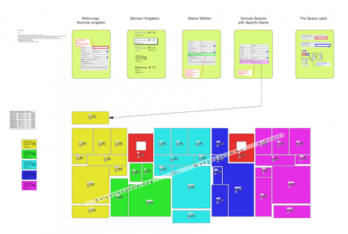
Hi Interesting Thread. Also i am also very interested to a facelift of script function palette. Some industries needs a lot of custom functions (easy ones like custom-tool in the tool menu) I have an own approach of organizing through one single palette, which have Favorite Scripts but can access to non-favorite scripts as well over the separator. Also there is a dialog, which allows to add and remove script to the favorite palette. Not finished yet (i will have to implement some presets to easy reset palettes to default) The scripts have to be numbered to keep position in they separator. Not very graceful but best i saw so far. I have a class palette_runner. Which runs a script by name. And in every seperator i call the scripts which starts with a sorting number till the next separator. And a script manager to manage the favorite sript-palette. So i have just one visible script-palette which i have to re-position. ScreenFlow.mp4 VSSM Vorgabe in Arbeit DC_bem scripts_leer.vwx
-
Create a texture resource from image in a folder
DomC replied to jonasfehr's topic in Python Scripting
Small Note to this I needed again the automated creation of textures. So far it seems, that the size of the texture is generally not consistent it the document unit is not in imperial units. Best solution i fount is to #insert at the beginning of the script unit_original_predifined = vs.GetPrefInt(170) vs.SetPrefInt(170, 1) #and reverd back to preview units at the end of the script vs.SetPrefInt(170, unit_original_predifined) -
Hello Possible, that the Objects got Broken (there was a Bug, Styled Marionette PIOs got Broken in Projekt Sharing under specific Circumstances lower than Version Update 5). Or maybe the Symbol Based Graphic is hidden in 2D and just visible in 3D View. There you had to change The Object inside the Symbol all on top view or all on 3D. If you mix just the symbol content of the activated view would be visible. If broken, maybe try to edit the Style if it is styled and look, what is broken inside the style. If so, try to find on an older Backup your script and copy it inside the style. Or if you did not changed the script, just the Symbol, you could re-import the style from the Download-Version and replace the "maybe broken" existing Style.