All Activity
- Today
-
Stable on m2max and 14.2.1 waiting for news about 14.5
-

Linking Record formats to referenced Excel worksheets
Jesse Cogswell replied to Tim Harland's topic in General Discussion
Because I don't know to leave well enough alone, I made a couple further changes to this plug-in. Don't worry, unless something is broken or someone wants me to add some crazy cool feature, this one is likely finished. The dialog will now remember the Show Hidden Records choice after pressing OK. This means that if you want to update your record data for a PIO, you won't have to recheck the box and reselect the Record Format, the dialog will automatically load your previous selection. After I did a test for a user trying to link to a Lighting Device (whose record has 100+ fields), I decided to revamp the Check Mismatch button. Before, it would launch an alert dialog for each missing record field, which was fine on records with only a couple fields, but is incredibly obnoxious when you have a hundred or so. It now launches a dialog box with a multi-line text box, so you can copy and paste out of it in case you need to really check for spelling/capitalization/extra spaces. Installation remains the same as described above. Link Worksheet to Record.zip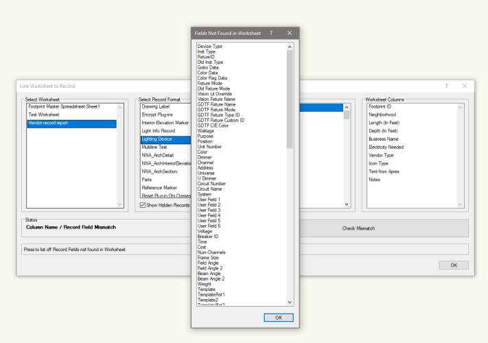
-
 Hi, ive been testing out the augmented reality and i seem to bee missing the core function of the utility. I cant seem to figure out how to actually scale and locate in the space? it seems i have to just manually "eyeball" the location and scaling by zooming and rotating. almost every other BIM augmented reality provides some function to print out a scaled QR code or something that references a point and scale within the drawing. for example. I can open the app, scan the printed QR code that is accurately placed in the construction space, and the AR will scale and locate the view in the field. is there any function like this that could make the Augmented reality viewer useful?
 -
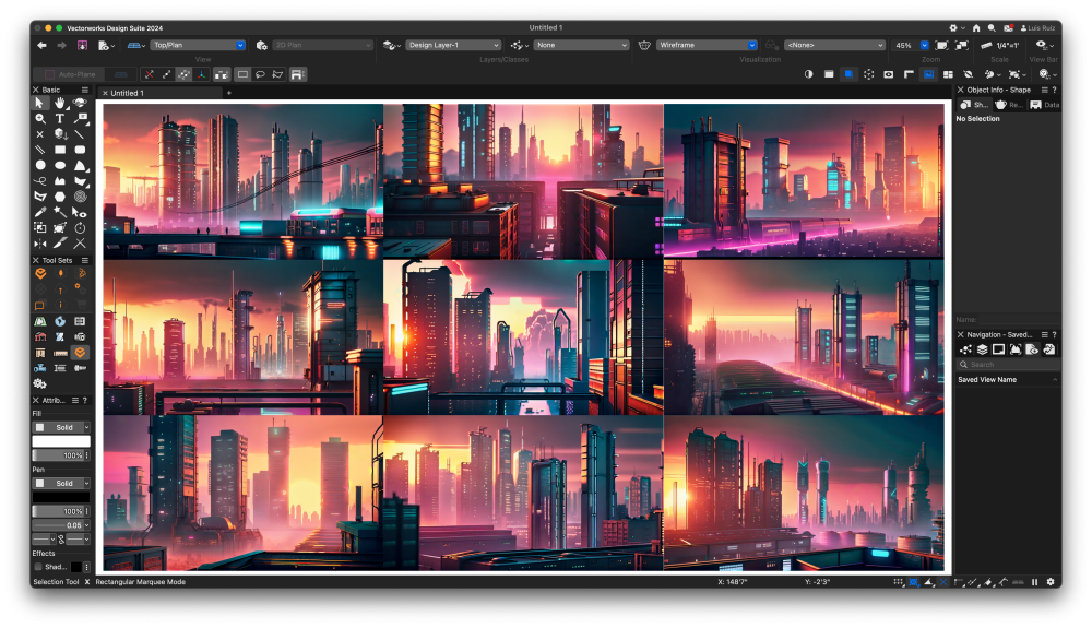
Anyhow. It is Saturday and my mind is on industrial futuristic cities. Here is a new approach at images. Prompt: Cinematic shot of an industrial city with tall buildings and cyberpunk style, in the background there is a futuristic building that shines like neon lights, at sunset, warm colors, highly detailed, high resolution I run the AI Visualizer by text only and get tons of ideas. Then I choose the one I need for my own project I have going on. Since last week a new AI plugin for Vectorworks was released and I am putting it to a great use. But Veras Lab only works on provided geometry/images. I am basically re running my AI image with this third party plugin and get newer results. Get the possibilities?

-
So far I've listened to different stories on how AI images are already been used by different designers. Some have been using this tech as assistance during their design/exploration phase. Some are only using it to generate images they can include on power point presentations. Others are just exploring materials. Some students create templates for board compositions. New friends are creating images for their own props (human figures, plants, etc). Images by text only is quite powerful, a way to test and refine your prompt and later apply it based on geometry. I personally ignore if there is a fixed recipe on how to include AI images in our daily work. I see some push back yes and I see a generation embracing it. I do notice there is a similar rhythm among these AI images among all the AI apps out there.
-
Again, love this technology, but what is the end goal for VW users? Perhaps there is not one. VW and AI visualizer appear to be two separate programs, but unlike VW and C4D, have no finality. One is text prompt Photoshop and the other a CAD system. Where do they meet?
-
Negative. This AI tool is not a replacement for raytraced renderings. These are just internal ways to explore ideas, entire dreams like metropolis, perhaps camera composition, materials, lighting, shapes. This tool is just image creation. What we are posting here are just samples of manipulating images. We know we'll get something no matter what, but how to make it move or produce something? that is the sole learning objective here. We could do cats and dogs just to learn manipulation of entire prompt sentences or keywords, but our community is different. Goal is to learn prompt composition / how much geometry is needed from vwx / level of creativity and propose new features that'd make this AI better. So far, the takeaway from this Futuristic Metropolis chapter are the keywords that trigger elements inside the image: Building, DNA, Cyberpunk, Dystopia, Skyscraper, Volumetric Light, Fog, Neon, Industrial, Domes, Tower, Cinematic lighting, Painting in the style of "x". The last images were a classical example of how by just typing the name of two mega known architects images appear, no matter the rest of the prompt. Zaha Hadid and Frank Gehry. So much to experiment with. Sharing your findings are greatly appreciated. Keep them coming here or in other AI topics. Let's keep learning.
-
 silkiki joined the community
 -
As much as I love this stuff, especially the bottom image.....is anyone using it for client presentation? The imagery is fantastic, but eventually you will have to produce a file someone can work with to build the structure. This technology appears much more suited to artists and the movie industry. When it becomes animatable it will revolutionize B-Role.
-

Parallelism Camera
shorter replied to htranbos's question in Wishlist - Feature and Content Requests
I assume 'parallelism' is not the same as 'perspective correction'? -
Export Files via Vectorworks Cloud Service
shorter replied to maxstk's question in Wishlist - Feature and Content Requests
Which is taking longer, RVT export or IFC? I would expect RVT to take longer and be unsuccessful to a point that it is better to export the IFC and get someone to open and save it in RVT, and get the conversation on to OpenBIM. -
Hi @grahami some time ago I posted a drawing here But I must admit this is 1753.257, standard stair. If you only need a placeholder in your drawing that is similar to the comfort stair you can easy cut this symbol to the desired outer dimensions.
-
Like I said, I am suggesting you forget about creating a custom symbol for the time being + try to make your window using the Window Tool. This should always be your first port of call. You only need to resort to making a custom window symbol if you are unable to make it using the Window Tool. If you are unfamiliar with the Window Tool have a search on the University for info e.g.: https://university.vectorworks.net/mod/h5pactivity/view.php?id=5640
-
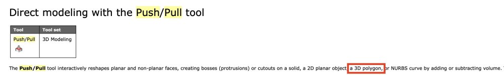
yes,- this is the correct definition, any planar 3D Poly. A triangle is always planar. 😀 It does not work with non planar objects.
-
From Help: It works with any planar 3D Poly for me...
-
@Benson Shaw Just stumbled over this, and was very suprised that this should work. Making a few tests I'm shure this works only with a 3D triangale made from a 3d polygon, since a triangle spans a plane in 3d space...
-
Hello, You should also check out @michaelk excellent Theatre Row plug in: https://www.verysmallgroup.com/vectorworks-plugins Cheers, Peter
-
Hi Alan, To answer your question the reason is because it is a 3D only symbol. If you cut the objects from the 3D component and paste into the 2D then the document preference of 'Adjust Flipped Test' can then work. Otherwise the objects are just planar objects in 3D. Troy is correct in that you should look at the ANZ Electrical Services tool. Right click on the page and go to the ANZ Video Tutorials to see the two about it's use. Cheers, Peter
-
Hello, What macOS are you on? Go to 'About this Mac' to find it. Then make sure you are on a supported operating system. Click here to check. Cheers, Peter
-

Crop edit not showing objects beyond crop line
Peter Neufeld. replied to MGuilfoile's question in Troubleshooting
Hello, My guess is that you have an out of date graphics driver. You are probably best to contact your local technical support so they can have a look at your DxDiag file. Cheers, Peter -

Auto Hybrid objects disappearing
James Dawson Design replied to James Dawson Design's topic in Site Design
OK, the cut plane elevation value was the issue. All AH had a 1000 vale, however the disappearing AH objects had a Z value higher than that. i.e. 2400. I changed the cut plane elevation value to 3000 and they now dont disappear. Time to learn a little more about this behaviour. -
 Gelec joined the community
 -
 Dear McCartney Design Team, I am very interested in the position you have available for a fast and accurate drafter. With 6 years of experience in interior design(3 years of retail design), I have been involved in all stages from initial planning to final implementation. During this time, I have developed a wide range of design skills and experience, enabling me to independently produce comprehensive drawing sets including plans, reflected ceiling plans, internal elevations, and shopfront drawings. I am enthusiastic about the opportunity to collaborate with your team. I believe that my skills and experience would add value to your projects, and I am eager to contribute my talents to your team. I look forward to discussing this opportunity further and hope to have the chance to work with the McCartney Design team. Thank you for considering my application.
 -
Another option is to turn the geometry into a hybrid symbol. This can be very quick using the 'Generate 2D from 3D Component' command.
-
Late reply, hope this is solved already. Here are some comments and a workaround. 1. Model>Extrude needs 2d source object(s). The selected 3d Poly will therefore not extrude and will instead generate that error message. 2. Push/Pull 1st mode should work with the 3d poly. Don't know why it fails. Maybe something wrong with the poly, the working plane, or ??? 3. Workaround: Put drawing in Top/Plan. and set the working plane to Layer. Select the 3d Poly, Modify>Convert>Polygon - result is a 2d polygon (or a group of 2d polygons - Compose them and ungroup), Model>Extrude to desired height of building, (or flyover view and use Push/Pull) Set Bottom z to 351.2 or as desired. Repeat for other shapes as necessary. HTH -B
-
Auto Hybrid objects disappearing
James Dawson Design replied to James Dawson Design's topic in Site Design
guess I will have to learn what cut planes are. You may well be correct.I -
 HCP joined the community
 -
Nope. I imagine the plug-in command would create the dialog with a pop up menu. I imagine you could tab to the pop up, but I'm not sure the arrow keys will travel the choices, but maybe. So, 1. select a hoist 2. initiate the command which shows the dialog with a pop up. (the dialog has to create the list of lengths 3. tab to the pop up 4. arrow key to the length 5. hit return 6. the command code writes the choice value into the field of the custom record. I think it would be easier to code just a query for the length that is then written to the record. compared to making the dialog and processing it, the ease in coding would more than make up for the typing of the length HoistHandle := FSActLayer; {assumes the hoist in on the active layer} LengthStr := StrDialog('Input cable length', ''); SetRField(HoistHandle, recordName, fieldName, LengthStr)