All Activity
- Past hour
-
 Bruna Moura joined the community
 -
Very useful indeed. If you wanted to go further you could add additional columns to your drawing label report so that you could control the properties of all the drawing labels in your file from the report. The report can then be exported to a template file to use in other projects. You can create similar reports for most other parametric objects. Reports have a wide range of applications, they were a big learning for me and really opened up the software to more than just a drawing.
- Today
-
Thank You. I have already started to implement some generic procedures into my programs. This one would be another good addition.
-

AI Visualizations-Thougthful discussions
VIRTUALENVIRONS replied to Luis M Ruiz's topic in AI Visualizer
Hi Bart, Yes I can, but tomorrow, thank you for asking. I have something I would Like you or anyone else to play with. In my career, I have modelled four massive site models, one on another planet. On earth, my site models are all historical. Below is one of them. This is the First Fort Henry, Kingston ON Canada. There is a fort there now and they call it "old Fort Henry, but it is actually new Fort Henry. The one in the video predates the current 'old Fort Henry". @Luis M Ruiz did some interesting work on a test video of mine, but the visualizer got the timelines mix up between WW1 and WW2. But the visuals were great. It includes Historical Architecture, defensive earthworks, cannons, etc. The prompts might be: Fort Henry French Design, Kingston ON. Predates current Old Fort Henry Kingston ON. Perhaps war of independence. French fort designs 1700 -
Hello @FMA, There are many things in VectorScript that could be easier than they are. The best way to combat this for your future ease and pleasure is to make small procedures/functions that simplify the tedious or clunky tasks that annoy you. In your case you'd like a LINE() procedure. Try one of these: if you work with individual XY values: Procedure LineP(X1, Y1, X2, Y2 :Real); { draw line from point (x1,y1) to point (x2,y2) } Begin MoveTo(X1, Y1); LineTo(X2, Y2); End; { LineP } Or, if you work with Vector values: Procedure LineV(P1, P2 :Vector); { draw line from point P1 to point P2 } Begin MoveTo(P1.x, P1.y); LineTo(P2.x, P2.y); End; { LineV } Put one of the above procedures near the front of your program(s) and use it like any built-in function. Eg., LineP(1, 1, 4.1, 0.3); { draw Line from (1,1) to (4.1,0.3) } or where P1 and P2 are type Vector: P1.x := 3; P1.y := -0.15; P2.x := 2.1; P2.y := 1.4; LineV(P1, P2); { draw Line from vector point P1 to vector point P2 } HTH, Raymond PS - In the vector example, when vectors are used to store 2D data, the Z-component is assumed 0, or set to 0, and is ignored.
-
No, (and kind of yes) The AI model used by the AI Visualizer ( I believe it was stated to be SDXL) is trained on 1024 x 1024 pixel images. It can work well with images that are not square as long as they have a similar total number of pixels (1365 x 768) The AI Visualizer will resample the input image down to something it can work with before processing. If you use a more sophisticated Generative AI tool, you can adjust the thresholds of how the ControlNet converts an image to lines. And, you can have that conversion happen on higher-resolution images before it gets downsampled to the working image. so you can kind of tweak the level of detail that comes out of the control net to be more or less strict with your starting image. For the black and white image of your sub above, I had to lower the thresholds to get the detail in the rear of the sub. Now, if we used a Hidden Line drawing of the sub, instead of a rendering, you would have a much more precise ControlNet to work with. Can you post that same view as a Hidden Line drawing?
-
You could assign different Classes for high vs low Walls and control their visibilities according to your viewport needs. If it is about standard Walls vs multi story height Walls it may be even worth to use different Design Layers. You can create real horizontal Section VPs, like generating from Clip Cube. But a true horizontal Section will not show the typical "top view" visual style look. And for a standard top plan view VP, you can set a cut height in Layer settings. But that will only simplify the look of the Walls below cut plane while higher Walls appear in the (fake) detailed cut look. So basically far from what you want to achieve. So as fa as I understand your problem, use Classes or Layers to separate your Walls and control visibility.
-
I have some high walls and some low walls. I only want to show the low walls in the plan viewport. Is there a way to set the elevation for where the floor plan is taken in a viewport? Like a section only horizontally.
-
I was first surprised that there is no simple Line function in VS, but I think youre just supposed to use LineTo() etc in combination with moving the pen position. That just seemed more complicated than nessecary to me, thats why I used the Poly() function, but I'm sure there is a good reason for it.
-

reduce the awkwardness of subdivision modelling
Neil Barman replied to Kaare Baekgaard's question in Wishlist - Feature and Content Requests
Might I be able to suggest that, for the time being, you double-click the Subdivision object when you would like to edit it? That will activate the Edit Subdivision tool. It may even turn out to be quicker than moving your mouse over to the Reshape tool or reaching for that tool’s keyboard shortcut. -

Show 3D axis labels - layer plane vs working plane
Oaktown replied to Oaktown's question in Troubleshooting
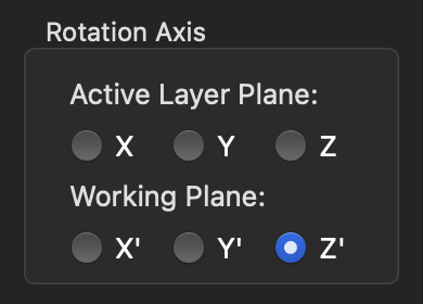
@markdd I think Vectorworks makes a pretty clear distinction between Layer Plane and Working plane and as far as I know especially in it moving in 3D and rotating in 3D command, that's the only place where X' Y' & Z' is used for both the layer plane and the working plane. The fact that the axes are labeled with a prime makes if very confusing if someone is trying to reference layer vs working plane when moving or rotating in 3D. Also, you're absolutely right that the layer plane is a working plane but it is the default working plane of that layer which is 1) as you say aligned with the internal X Y & Z axes and 2) has been named the layer plane as a norm so it's important that Vectorworks be consistent with its naming & labeling conventions. It'd be interesting to know what the VW team replies Frédéric "Oaktown" -
AI Visualizations-Thougthful discussions
VIRTUALENVIRONS replied to Luis M Ruiz's topic in AI Visualizer
Does the size of the image (within reason) affect how the Visualizer will respond? -

Show 3D axis labels - layer plane vs working plane
markdd replied to Oaktown's question in Troubleshooting
You may be technically correct if the labels refer to just a static plane. However, what you are technically seeing is a Working Plane like any other, it's just that it is aligned to the Internal X, Y, and Z axes. If you click on any one of the axis lines, then the working plane widget will be activated, and you can move the working plane to wherever you need it. You are correct, though, until the working Plane widget is activated, then yes, I think X, Y, and Z ought to be what the labels should read. It is certainly rather ambiguous. -
I am confused as to why the axis labels show up as X' Y' & Z' when [Show 3D axis labels] is selected in the [Snap to Grid] tool and you are on the Layer Plane . Shouldn't it be X Y & Z for the active layer plane since I was under the impression that X' Y' & Z' was reserved for working planes as shown in the Rotate Object in 3D tool Frédéric "Oaktown"
-

synched ConnectCAD-Database for all users in the Workgroup
v.fl82 replied to v.fl82's topic in ConnectCAD
The Problem is, that the team wants to keep the User Folder on their own workstations. But if i create a new device and save it to the Database, it will create a new txt-file in the local User-Folder. Is there a way to say ConnectCAD, where (in Which folder - like a .txt-File in the Workgroup-Library) the new Device should be added, rather than always save it in the User-Folder? -
We are a total of 5 planners in our team and would like all new devices created by us (via the Device-Builder Tool) to be saved in a shared database (Workgroup-Library?). Ideally, this database should always be accessed automatically when Vectorworks is started. How could this be accomplished? The aim is to avoid having to do the work twice or three times by not having to create the standard devices that are used in projects each time. We also use the automated creation of devices via a worksheet (ConnectCAD-Update-Create Devices from Worksheet). To make this faster, it would be good to have just one shared database. I look forward to your feedback.
-
 Trstn123 joined the community
 -
If you still have them I would LOVE to take them off of your hands. I live in the US, but am happy to pay for shipping. I loved using and learning Vectorworks in college but have never been able to afford a license, so I haven't been able to use it since my student copy expired. Your 2008/2009 copy will get tons of good use if you're still willing to part with it.
-
Hi @Sam Jones and @JBenghiat thanks for weighing in on this! Will have a look into the link.
-
 JohannesDavidSchmid joined the community
 -
 KevinF1973 joined the community
 -
I know I will sound like a broken record,but….it is totally Impossible to give you a solution without seeing your file… If you are able upload the file, or a portion of the file if it is huge, so we can have a look 🙂
-
Hi there, I've had this issue come up a few times over my last few projects. I've previously managed to find work arounds but never solutions. Can anyone tell me why my hardscape objects render as black polygons rather than the textures I've assigned them? I have tried different renderworks styles, changing the individual textures on specific faces of objects, editing the style to change the texture used and probably a few other things that have been forgotten in fits of desperation! My only solution so far has been to use a top/plan view but that isn't an option when I'm trying to produce 3D renders. Please see attached pictures to see the difference. Any help/thoughts/advice would be greatly appreciated. Thanks in advance


- Yesterday
-
I think you found it. You would then add items to the menu
-
Don't be shy, Pick the tall one and post it online. It's Saturday, gives everybody something to critique. The Ai visualizer has been taking up some time. It's good to see good old hard work paying off. Paul
-
 Paul You choose one and I will send it to you via direct message 🙂
 -
Yes, why don't you post a closeup. They look great. Paul
-
Hey Paul 🙂 Yes I did render that scene in C4d. I sort of default to C4d for all interior Renderings. Just force of habit these days. But yes, all of what you see was created in VW. Even those cure little 3d fishes and the coral and plants! I imported those items, actually, did not model them. Too much work !🙂 I can upload a closer view of one of the aquariums, if you wish. I just wanted to do a wide view so folks could see all of them.
-
HI Kevin, Those are fantastic. I am assuming you rendered In C4D, but did you build in VW or C4D? Paul