
aage.langedrag
-
Posts
86 -
Joined
-
Last visited
9 Followers


-

Length of railing and fence as a property in IFC?
aage.langedrag replied to aage.langedrag's topic in General Discussion
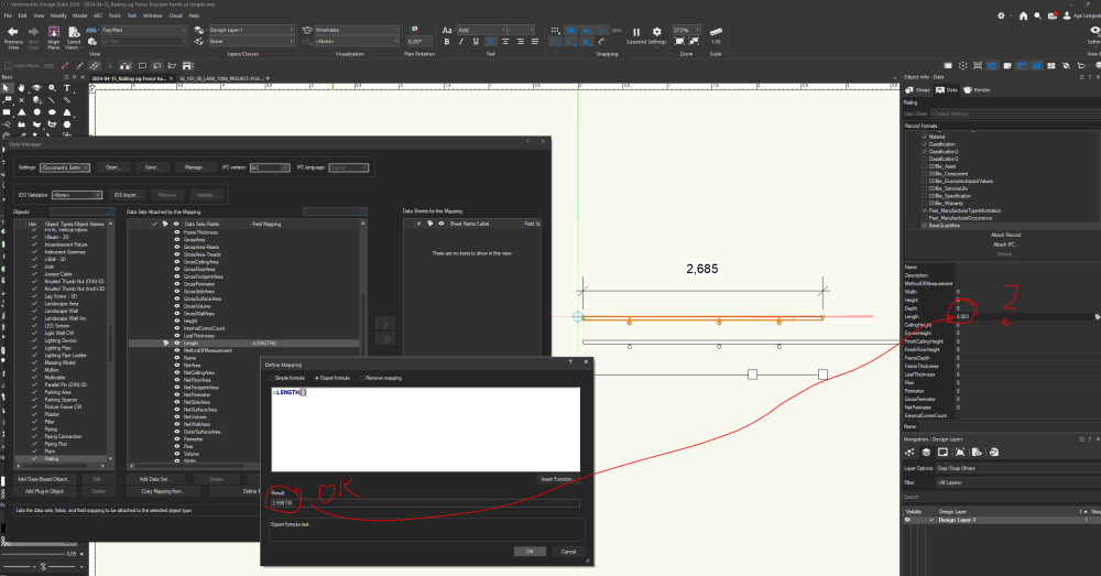
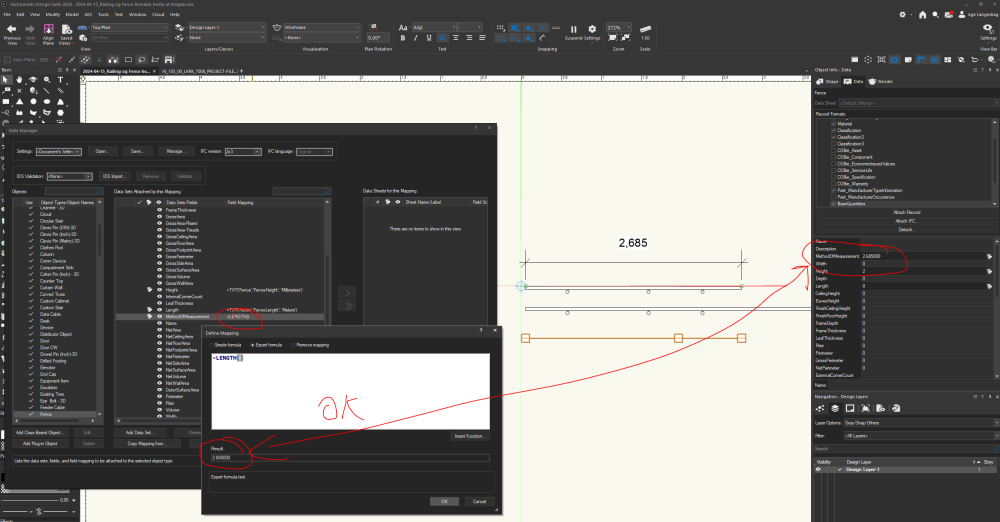
Hi @Scott Campbell, Thanks for the reply where you show the Fence specific parameter. I keep forgetting that I have to look for these under "Expert formula". When I, who believe that I am quite interested in finding solutions, am "unable" to find this, I think that it should have been easier to find these parameters. Why isn't this simple in the "Simple formula" on relevant object types?????? The most relevant properties for all object types should be the properties that are always found. I also cannot see the length of the railing or Fence when I mark the object and look in OIP. Isn't this standard info? I greatly appreciate Vectorworks' great possibilities, but I am equally amazed at how much time I spend looking for very simple features and functions that I believe should have been visible to me without me having to test and search and search for help. When it comes to rounding off the length of the Fence in the example model, this must be an error in the program. I haven't done anything special. I only selected the standard object type from the library so I wonder if the program doesn't understand that the file is set with Units in meters? -
How do I get the length of railing and fence as a property in IFC via Data manager. Does not work correctly in current version of v2024. "Lengte()" shows correct for Railing but wrong for Fence when I read this in OIP. 2024-04-15_Railing og Fence hvordan hente ut lengde.vwx
-
Hi @Scott Campbell I saw that this whole thing was misleading. Have tried to change the heading and be more clear in the original text.
-
Hi @Scott Campbell. Watch this video and you will see that when I create a grade on Design Layer-2 and snap to Grade on Design Layer-1, the Grades on Design Layer-1 are split up. In many cases, we want to be able to see Grades from a Designlayer and snap to but not split up. 2024-03-11_12-27-21_v2024 - Grades.mp4
-
Big wish that Grades on different design layers can snap but not connect to Grades on other Design Layers. I work with several alternative solutions on different Design Layers. Very frustrating that Grades on Design Layer-01 connects to Grades on Design Layer-02 and divide that Grades . Suddenly, I have divided the Grades on another design layer. The elevations have also been altered and "destroyed". I wish I could have a setting that says that Grades should only connect with other Grades on the same Design Layer or that I could choose from a list which Design Layers can be connected.
-
Archicad dwg files to a referenced VW site model
aage.langedrag replied to Minna's topic in Site Design
Here is a copy from a discussion on Beta which should also be available to everyone. The case does not contain content affecting Beta. «…..The best thing is to be able to go back to whoever sent the file that is wrong about sending a new file that uses the project's common internal datum. We had this problem before, but in the last 10 years, all projects I have contributed to have more or less got this in place. BIM coordinator in the project ensures that the project has a common internal coordinate point BEFORE the technical engineers start working. In a construction project, it is often the Architect who is responsible for determining an internal coordinate point for the project that is located so that ALL disciplines who contribute to this project must have their objects placed with positive coordinates. The shared internal zero point is then often at the bottom left of the project's boundary. This also becomes our internal zero point in Vectorworks so that IFC files from us and other disciplines match before starting the project. I know that those who use Solideworks also struggle with z-axis orientation, but I have been involved in this in the past. A few weeks ago at the latest and they manage to solve this as well if we make demands. I had to search Google myself to find a solution for them, but the solutions are there. You probably know this, but just want to clarify if others are reading this how important it is that we who use Vectorworks look at the Vectorworks local zero point together with the project's local zero point when we work with IFC. There, Vectorworks has not been clear in its presentations as far as I have been able to see. Therefore, we should look more at buildingSMART's description of the local zero point. Sorry, the document is in Norwegian, but use a translator and you will understand what this is all about. Thought I'd also seen an international document in English but can't find it now…..» bsnp_georeferering_20100415_EN(Google translate).docx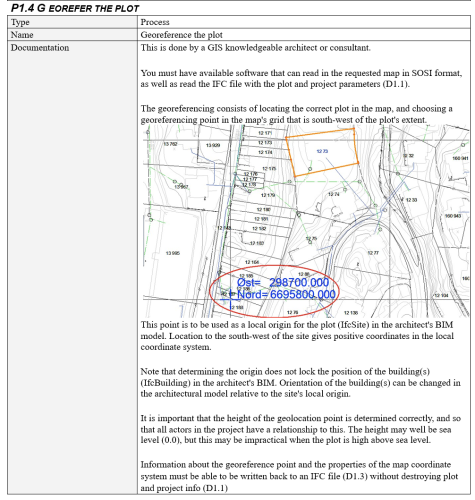
-
Archicad dwg files to a referenced VW site model
aage.langedrag replied to Minna's topic in Site Design
Hi, Not sure if this has been mentioned earlier in this case. ALWAYS open dwg from ArchiCAD in Civil3D/AutoCAD before importing in other programs. In the Nordic countries we use metric units. Architects in millimeters and Landscape architects in metres. Check the unit of the drawing on known dimensions. Most often you see by measuring that the file from Architects delivered from ArchiCAD is then in millimeters. Then comes the fun part. Check "Units", even if the file is drawn in millimeters, the dwg from ArchiCAD ALWAYS comes with "Units=feet". You must change this to millimeters without changing the geometry. Save the file and import this file into Vectorworks. -
Hi @Benson Shaw, Thanks for the clarification and good video. What you are showing is that the function does not work. The working method you show is far too imprecise and not least time-consuming. Other software has technical solutions, so I have faith in Vectorworks' programmers to give us functions that work as they should. Until then, I will not use the current solution and I hope the function is removed from the program so that more people do not spend precious time on something that does not work.
-
.ids (information delivery specification) file import
aage.langedrag replied to gester's topic in General Discussion
https://www.buildingsmart.org/what-is-information-delivery-specification-ids/ -
Multi-discipline Collaboration with Revit BIM Model and Vectorworks.
aage.langedrag replied to dcg's topic in Workflows
Hi @Poot, Thanks for passing on my presentation. Completely agree with you that the current solution for landscape architects and BIM is via Vectorworks. As you will see in my presentation, much of the work I show was done in Autodesk Revit while we have moved the entire model over to Vectorworks and further built the model so that it contains all the information we need to build according to the model without the need for drawings. We have a few principle drawings which in the future can easily be replaced entirely with a model. Maybe I can update the presentation sometime and show completely how the model is now used for construction? -
Maybe it wasn't so clear in my previous answer, but for those who want to make suggestions and contribute with desired solutions, I can recommend becoming a Beta tester. Life gets a little better to live 🙂
-
Workaround for exporting site model to landxml.
aage.langedrag replied to Knut Andreas's topic in Site Design
Are you a BETA tester? Try to see what there is of discussion and solutions there, also VW and DWG. Yes, I want to be able to deliver "LandXML", but when it's not easy, we have to look ahead. What will the file be used for? Basis for new terrain surface in other software for planning? Use DWG, DXF or IFC. If the file is to be used for machine control and construction, the matter is solved very easily. "All" contractors and landscape gardeners in Norway use PowelGemini. PovelGemini can extract machine control surfaces, lines and points directly from IFC which they use to build from. Remember that in most projects there is a requirement that everything put out in the field must go through a company with PRO and UTF approval. (In Oslo requires class 3). I don't think LARK is always aware of the responsibilities they take. Therefore, we send our model as IFC with the correct geometry and information via an approved company. Forget KOF, DWG and LandXML and start using IFC which is here to stay. Reduces the number of file types. The same file that is delivered for planning is also used for construction. Could this be a solution? AGAIA builds and obtains construction data only from IFC at New Hospital in Drammen.AGAIA - Drammen hospital Very satisfied with solution and method. -
Hi @Poot, No, I have not received feedback on this, but I do not think it is a function that can be used. Based on the feedback in this case Site Modifiers - Batter slope with constant slope I guess I can't trust that this will be correct in this case either. Guess we'll have to wait until we get another function in Vectorworks that works as desired.
-
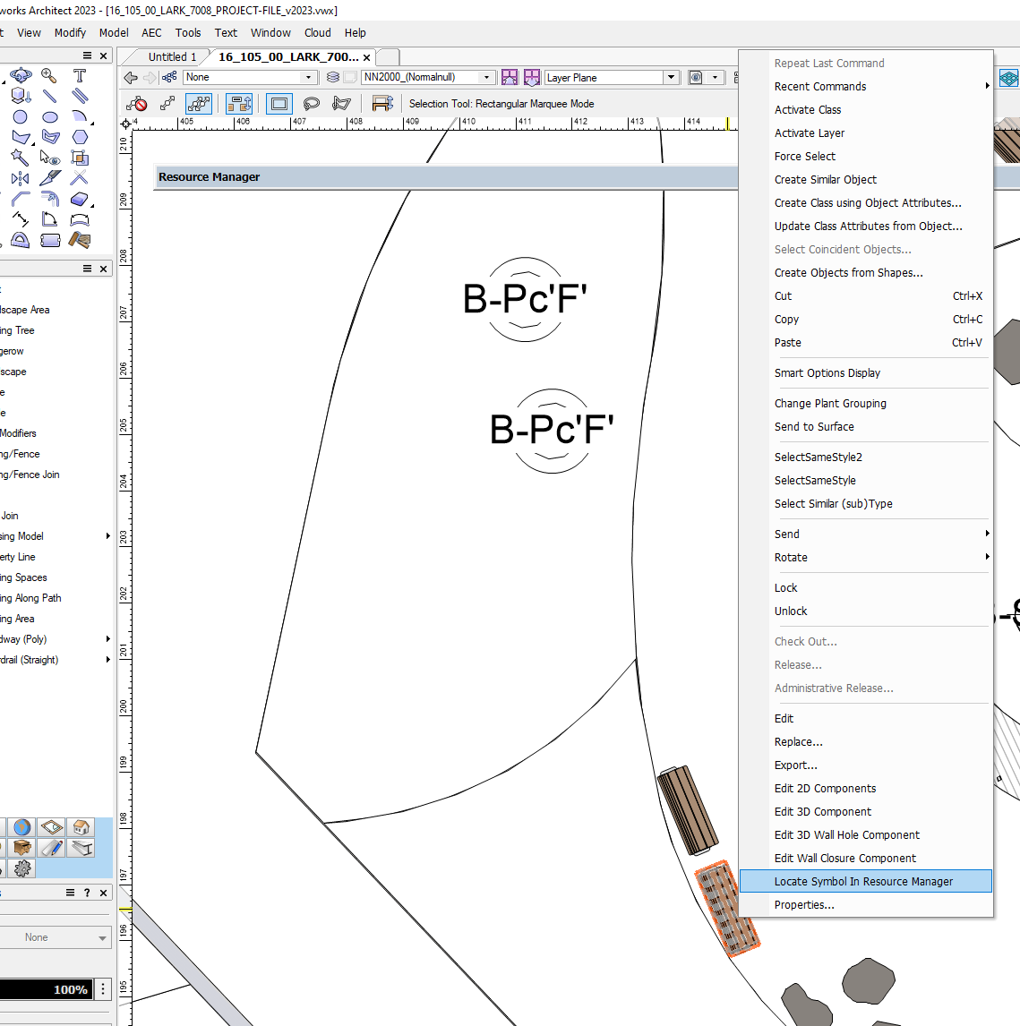
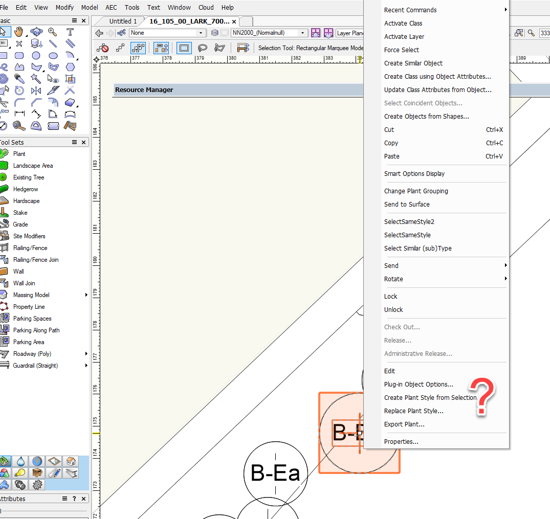
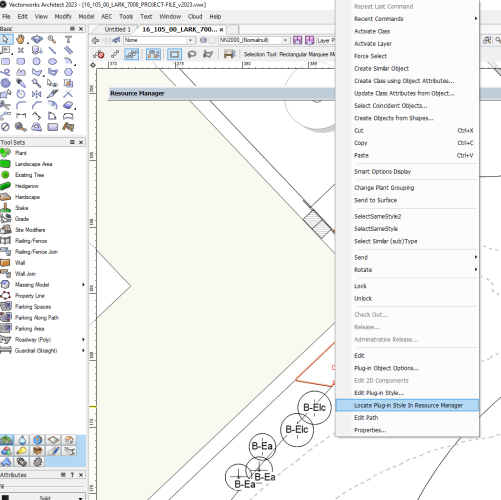
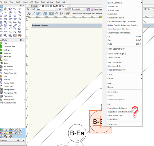
Why doesn't this work? Landscape Areas, Hardscapes, Furniture, etc. can be marked in the model, right-click and select the functions "Locate Plug-in Style in Resource Manager", "Locate Symbol In Resource Manager". Why not with plants? In a large project where you manage as much information as possible on objects by Style, I want to be able to quickly find the objects in Resource Manager. It is very frustrating when this does not work for plants.

-
Maybe your wishes are on their way sooner than you know? 😉