Search the Community
Showing results for tags '3d'.
-
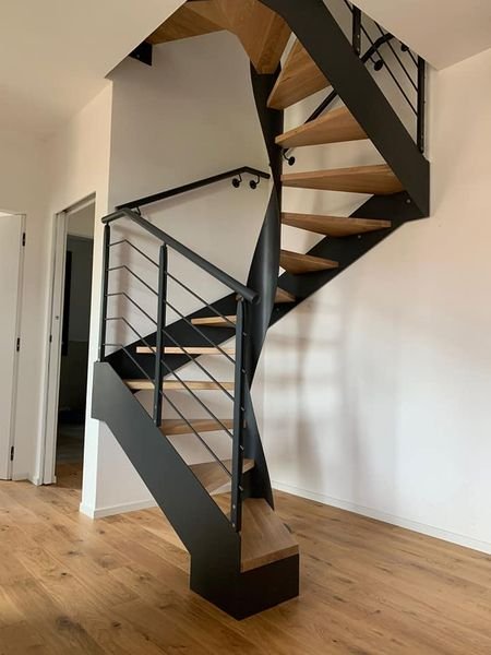
Hello, Does anybody know how to build a squared spiral staircase in Vectorworks 2024? I've only been able to build a round one with the 3D stairs tool... Thanks in advance 🙂
-
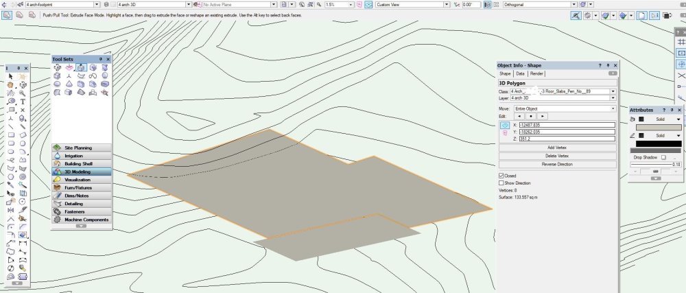
I want to draw a very simple house massing model, I have never made anything 3D (except for mining area landforms) in vw before as have never needed to - as it seems so much simpler to drawing most 3D in other platforms but I want to use Heliodon so I need a mass model and so far I can't get the 3D push-pull tool to do anything. I think everything's set up right: I have a planar 3D poly I think view is correct I select the 3D poly Press the Push-Pull icon .. and nothing happens when I try and drag selected surface, it feels dead / unresponsive. What am I doing wrong? System is Windows 10 64 Home, VW 2018 I've just tried Model>Extrude and I get the error "there were objects selected that were locked or illegal..." I drew the shape in VW, it's planar and very simple.
-
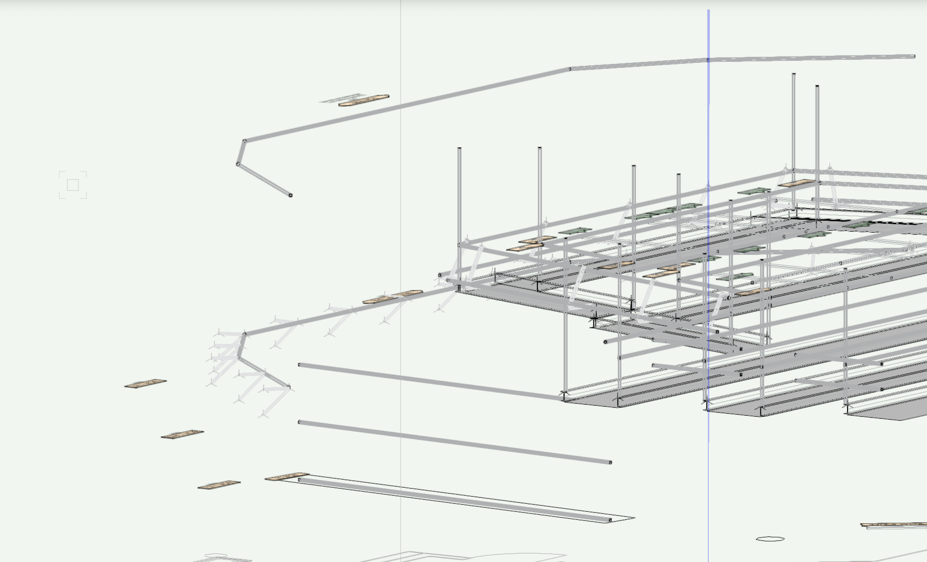
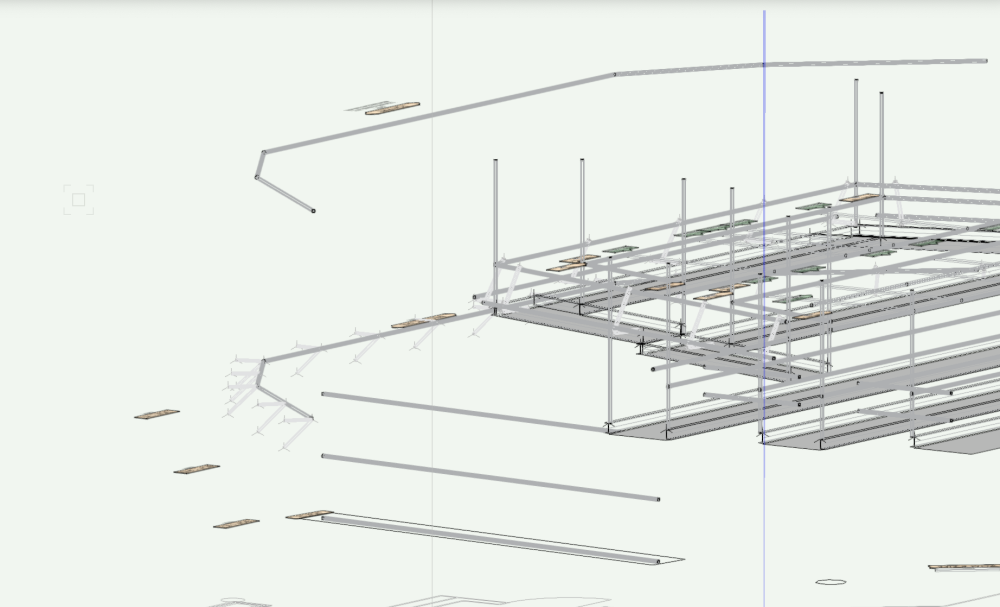
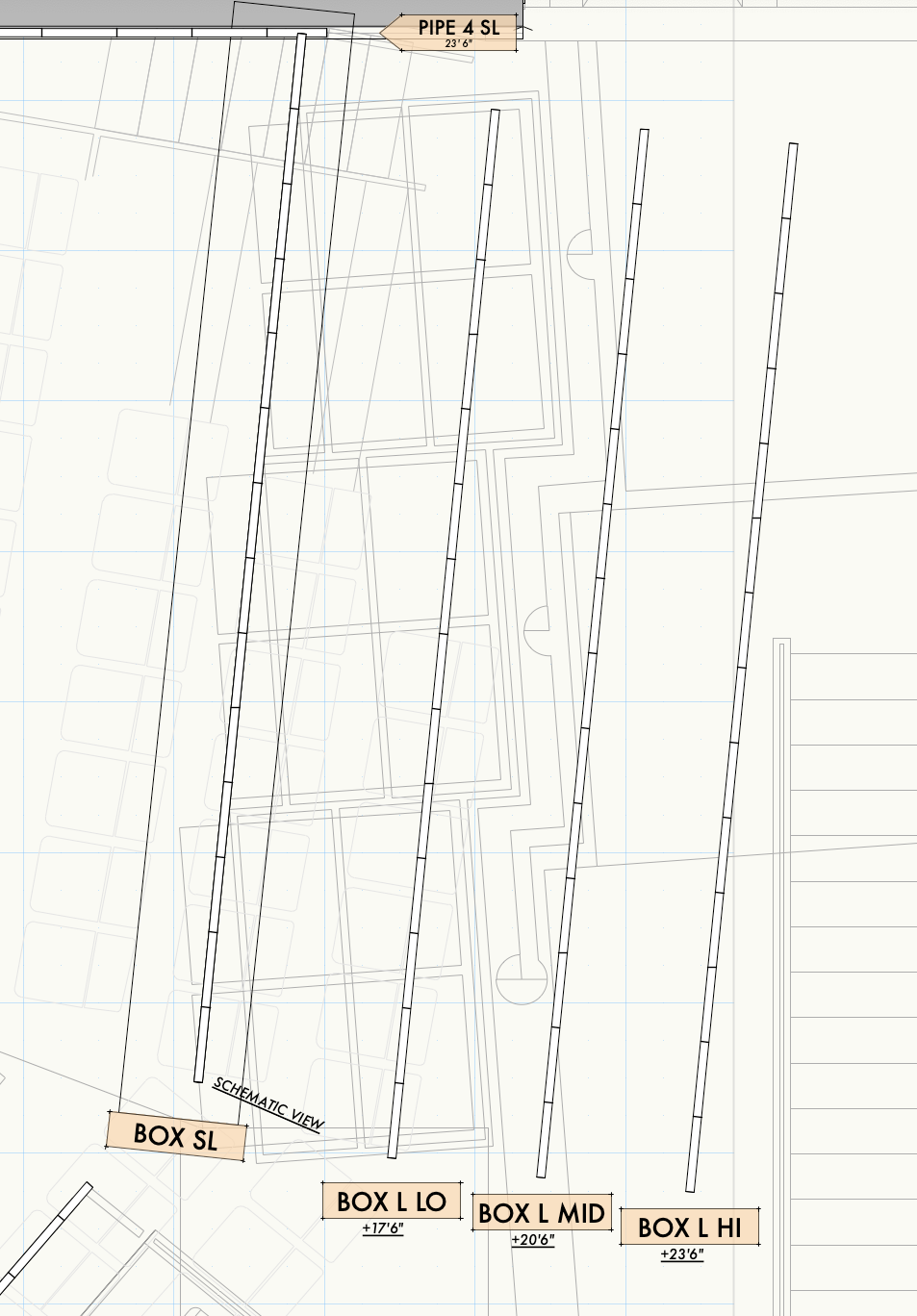
Hello community! I have a theater space with box booms stage left and right, and a balcony rail and ceiling pipe that exist on top of each other. I am trying to find a good way to draft these going forward so I have a good file to send to guest designers, and I think schematic views are the best way to do that, but I have a few questions. -When I delete a light off of the Schematic View 2D pipe, the light on the original hang pipe stays there. Do these not stay in sync? I tried updating all schematic views and that didn't help. When I delete the lighting instrument off the original 3d pipe, it deletes off of the schematic view, but this won't be easy to do when lights are stacked on top of each other (the whole reason I want to use schematic views). -I would love the original hang pipe and light fixtures to display as 3d objects or a shaded object rather than their 2D view, so it's easier to delineate between the schematic view hang pipe which should be modified, and the original pipes drafted on top of each other. -Should I be using the ladder pipe tool for the box boom application? Does that apply to the balcony rail/ceiling pipe as well? I very much appreciate any help! Thank you!
-
Hi All, I've reached the point where I'm trying to extract some 2D images from our first full 3D modelled project. I've done a bit of googling around but can't find any clear definitive advice about how to create 2D plans. Also it would be good to know any potential pitfalls or things to watch out for when modelling to achieve good 2D plan results.. As far as I can tell there are two options: 1- Make a viewport in the Traditional 2D way, as previously done when drawing in 2D. i.e. when creating a second floor plan, only the '2nd floor plan' layer would be turned on in the viewport. Any info from layers below (i.e. a ground floor roof, a Staircase drawn on the 1st Floor layer but which arrives at the 2nd floor plan) would have to be drawn on separately. Not ideal or very 'Smart' really, could end up with some inconsistencies. 2- Make a Section Cut viewport using either a) the section cut viewport tool, or b) using the clipping cube tool. The whole model would be turned on, so elements from below will appear. Care would have to be taken to get a good 'clipping' distance. Advantage is that it could show information from below, such as lower level roof structures or double height spacers. But this can include information you don't want to see sometimes. For instance, in a second floor plan I may see some outwards opening door swings from the ground floor plan below protruding out. Any advice from some of you seasoned 3D pros would be great! Thanks, A
-
Hi forum, Is there a way to make polygon based - image prop for plant objects? I know there is a way to generate from image. I am looking for polygon based approach so I can have more control of line and fill color. Something like what Revit is having now. Thanks!
-
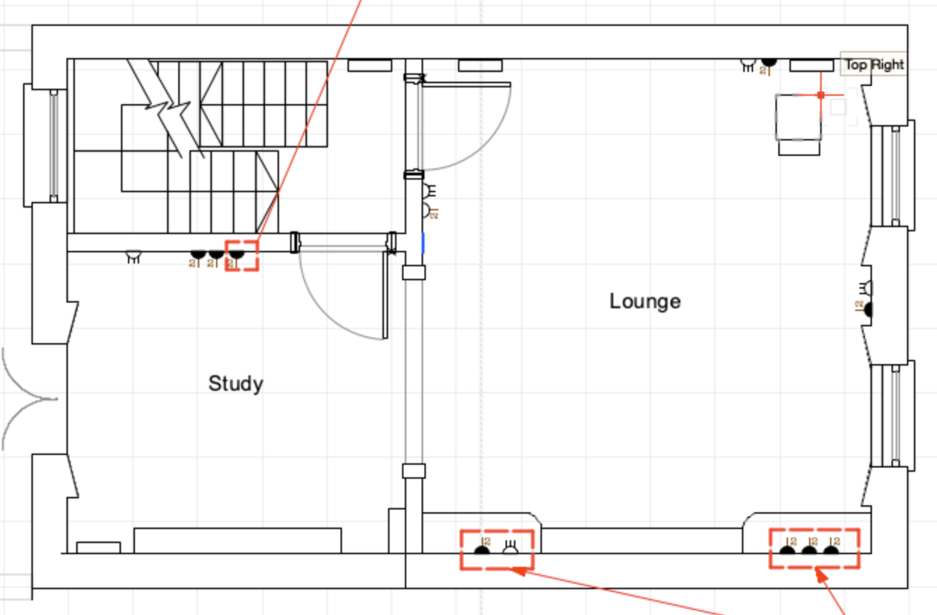
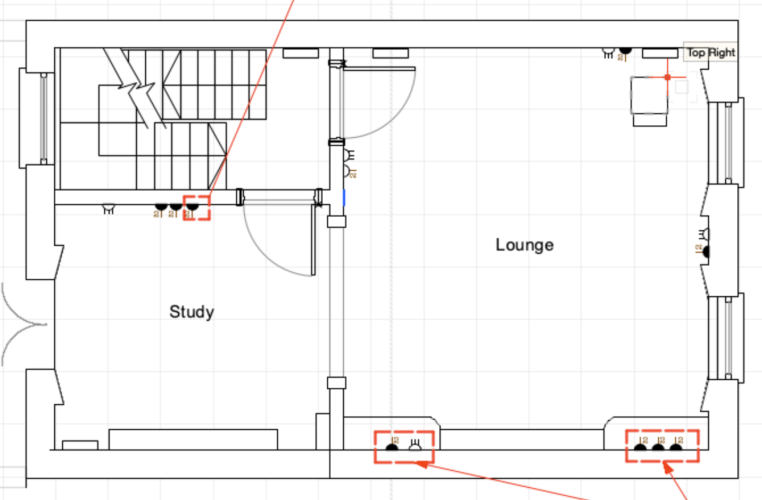
My studio is looking to use Vectorworks for both 2D and 3D plans. Would I have to assign a 3D symbol to all of my existing 2D ones? or are there easier ways to put sockets, switches and lights into a plan? I've attached a screenshot of what the plans usually look like but these are only in 2D.
-
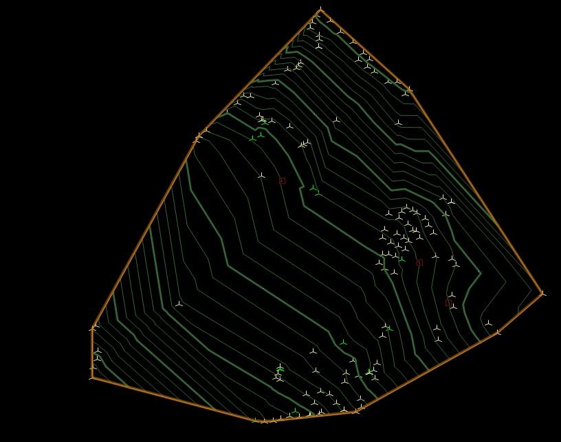
I have a very simple site model - made from 3D loci. I'm trying to export the resulting contours from the site model as 3D. But result is always 2D - hopefully there is a method. I have tried just exporting the site model and have tried via Edit Existing Site Model COntours and selected and exported - but same 2D result. Using VW2018 on Windows.
-
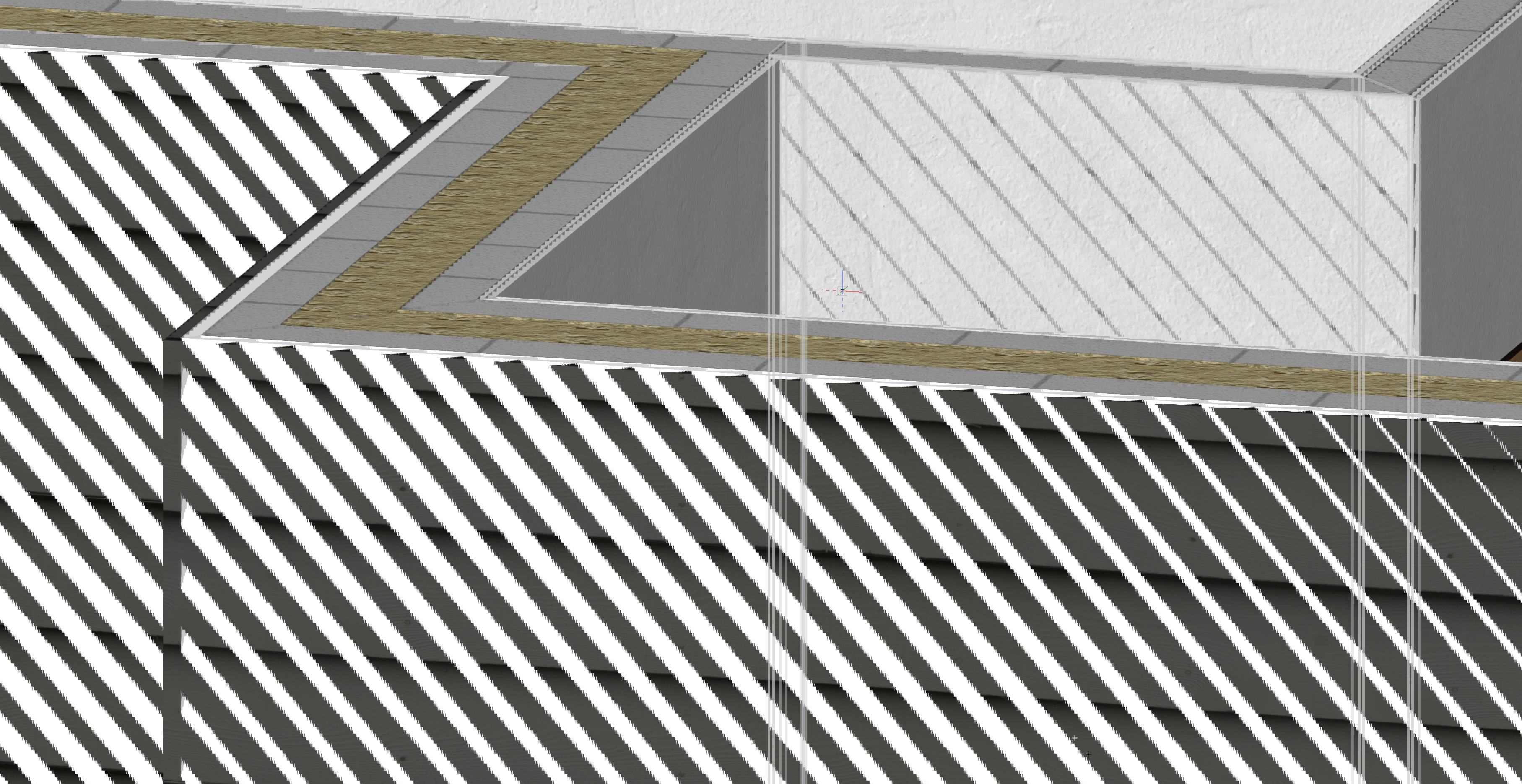
In this video I try to use the reshape tool in adjust parallel edges mode to adjust the bottom edge of an extrude to align with to top face of another extrude below, however Vectorworks fails to acquire any snaps on the extrude below. I would expect snap to point to acquire the top corner of the extrude below. I would expect to be able to hit T to constrain the movement to the vertical axis and then be able to snap to the intersect of the constrained line with the top face of the extrude below. I switch to orthogonal mode and rotate view to match the plane of the extrusion hoping that I might pick up a point somewhere but I don't get any snaps at all on the object below. Why is this not working? As you can see I have all my snaps turned on apart from grid snap. I'm not sure if this is a bug or a feature request. But it feels like it must be a bug because if I come out of the extrude and draw a line from the point at which the reshape handle was at to the top face of the extrude below the snaps work as expected. If I then go back into the extrude I'm able to use reshape to edit the polygon inside the extrude to snap to the point at the bottom of the line. 2078744964_ScreenRecording2023-01-31at12_27_09.mov 376387456_ScreenRecording2023-01-31at13_06_34.mov 1311394037_ScreenRecording2023-01-31at13_09_11.mov
-
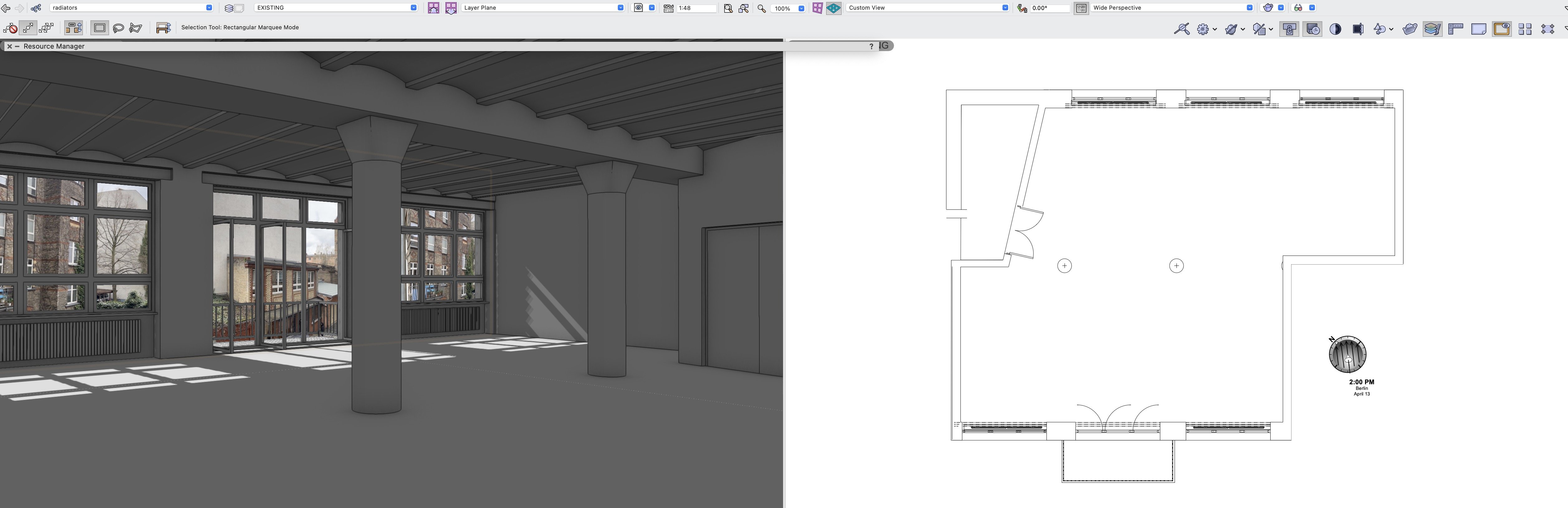
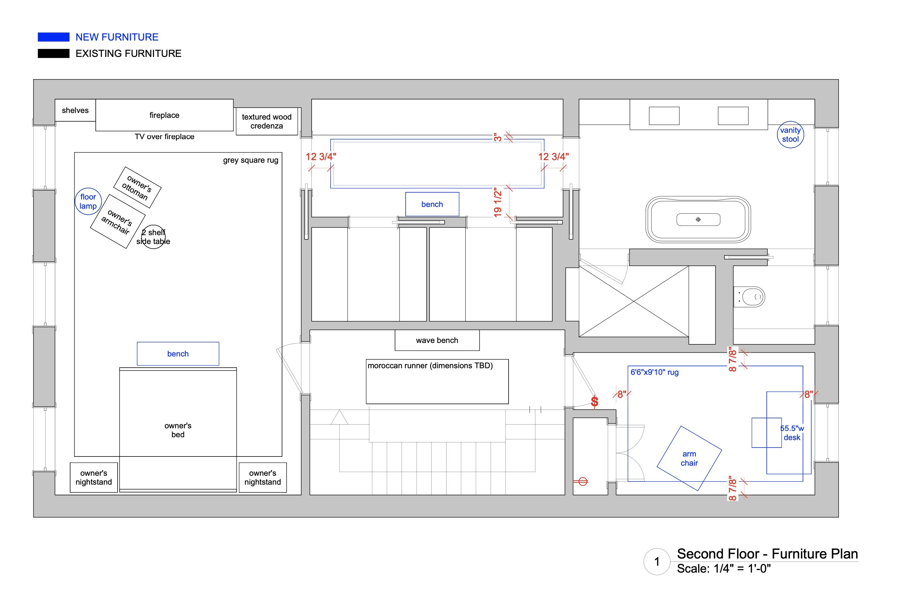
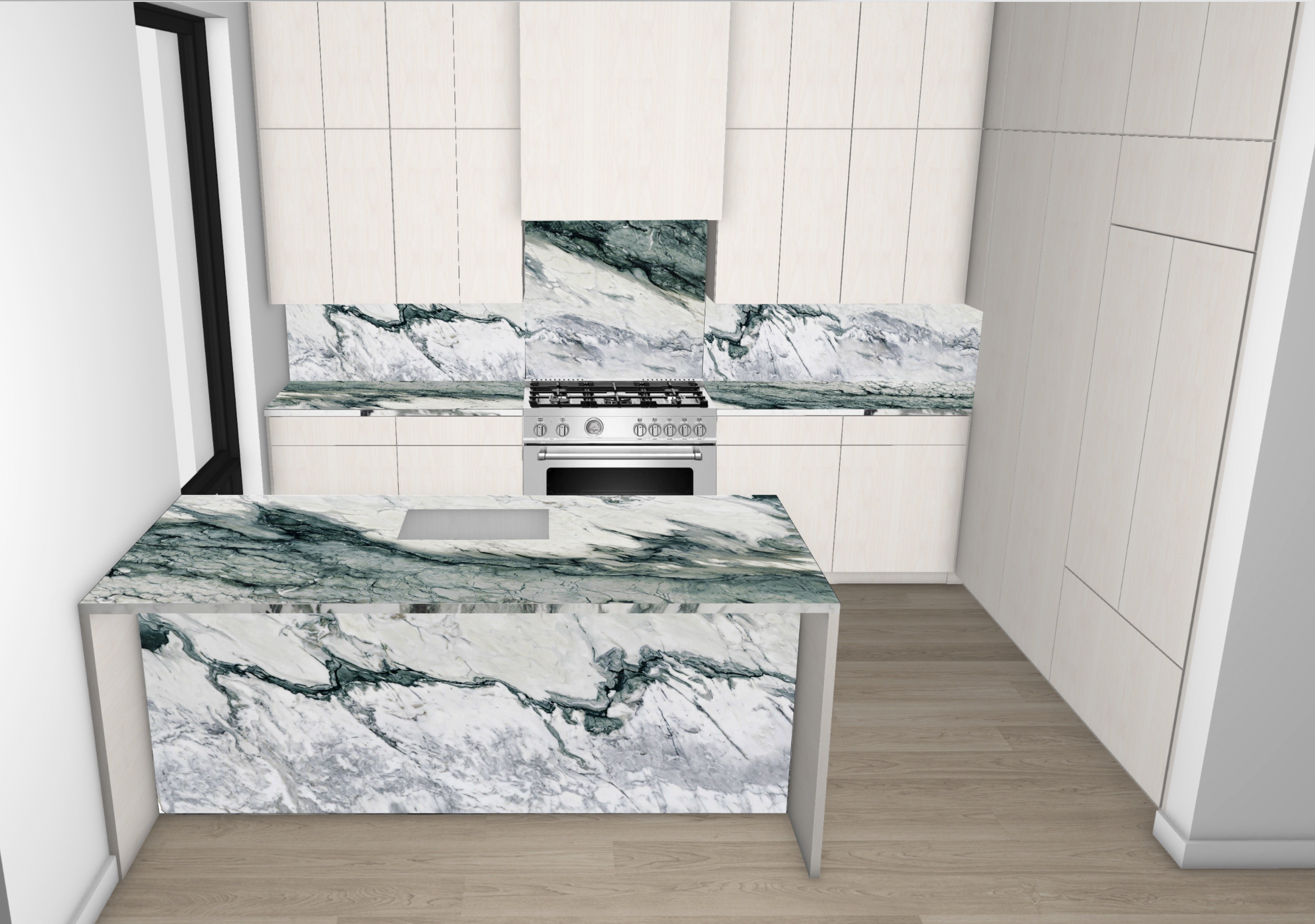
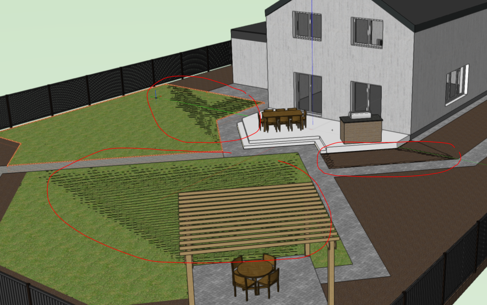
We're looking for help with implementing design changes in our Vectorworks scenes. For example, adding new furnishing elements to the scene, changing walls, adding textures, etc. Please see the examples of what our outputs usually look like. We don't need photorealistic results but the ability to modify our designs quickly. If design development is done, we can also talk about more realistic renderings. This is an ongoing task, and we seek professional and reliable help!


-
 Hi All, I'm gradually getting to grips with 3D Vectorworks, but still finding some simple things frustrating, and I'm sure its just my lack of knowledge! Is there a way to move things to a specific 'global' z height? For instance, I want to move an object to sit on 'z=0', but there is a bunch of geometry around there which makes it hard to snap precisely. Or, I want to move the object from within an awkward 3D view. Any tips or advice?? A
 -
Hi, im having trouble with the text that I want to have on my architecture document. Im trying to write some text and putting it on a wall vertically in 3D, I am able to get the text to 3D but when I try to move the text or modify - rotate - rotate vertical, the text goes at some angle and is not vertical and Im unable to put it on the wall, can someone give me advice? Best regards
-
I am trying to produce a 3D model of my 2D plan. I have decided to take the 2D polygon hatch areas and turn these into Hardscapes. This has worked, but when I look at them in flyover mode they are only in wire frame, not solid. I only want them as white blocks. I think it has something to do with what class they are in, but I am completely confused.... I changed the Site-DTM-Modifier class to a white fill and then they all come in as black. Which I don't want, I want them in white. Thank You
-
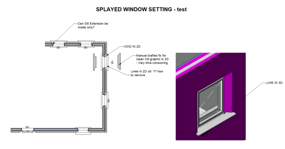
 HI, Does anybody know how to solve this SILL Problem in VWX 2023 ? Trying to move from 2D to 3D and encountering the following problems with Sills. Am testing V 2023 and Window Sills within Splayed Wall. IN 2D 1. Unwanted Lines from external wall across sill EXTERNALLY 2. Unwanted Lines across Sill INTERNALLY 3. Cannot Control Internal Sill shape or dims - Length is exactly the same as external sill offsets 4. Void in 2D between Splayed Wall and Cill. IN 3D 1. Unwanted Lines to sill Externally 2. NO sill INTERNALLY unless Jamb extension used 3. If Jamb Extension used it extends externally into void 4. Cannot see anywhere to control the Shape, Dims, extend of Sills independently. - for Inside and Outside or remove unwanted lines. The only way I can see to do this is for 2D graphic to draw polygons internally and externally for EACH WINDOW , but this won't read using Clip Cube so the manual process needs to be repeated in all sections. Surely this laborious workflow ( if only option) goes against what they're trying to achieve with more interactive, time efficient design workflow ? - Any assistance gratefully accepted . Frank
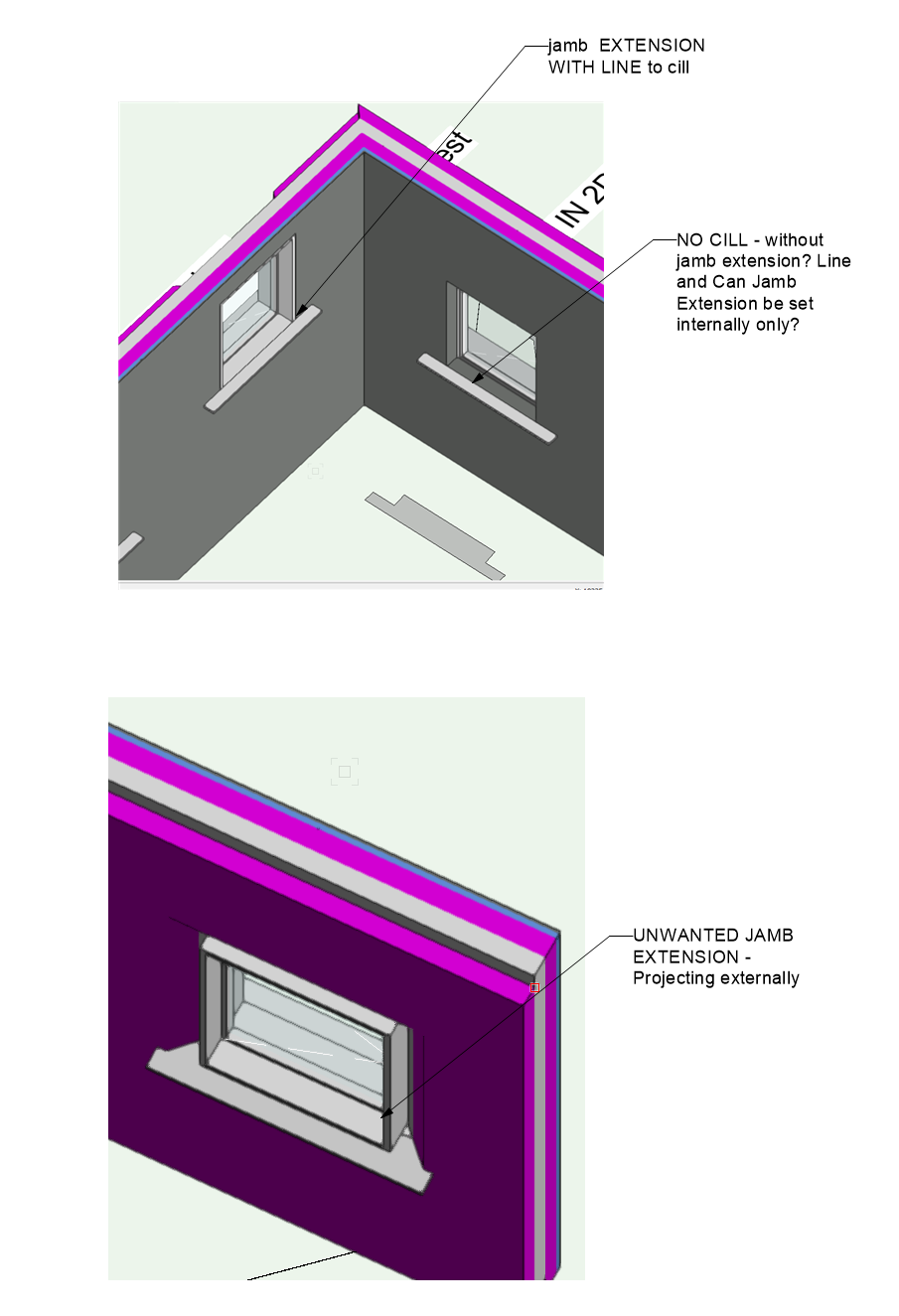
-
Hi all, I have an issue that pops in every day, although every time I restart the file and vw, the file goes back to normal but after a few hours of work it pops in again. This happens both on windows and Mac. Version of WV is 2022 SP3.1 (build 646432) 64bits (Mac) windows I forgot to check but it's updated to the last version so I'm guessing the same. The file resolution was in 240dpi's but then I changed to 72dpi's but still did the same. Sometimes happens that I work the whole day without this issue shows up, but like today it's showing quite regularly. Any ideas how to fix this? When I start orbiting the file shows like this If I zoom in

-
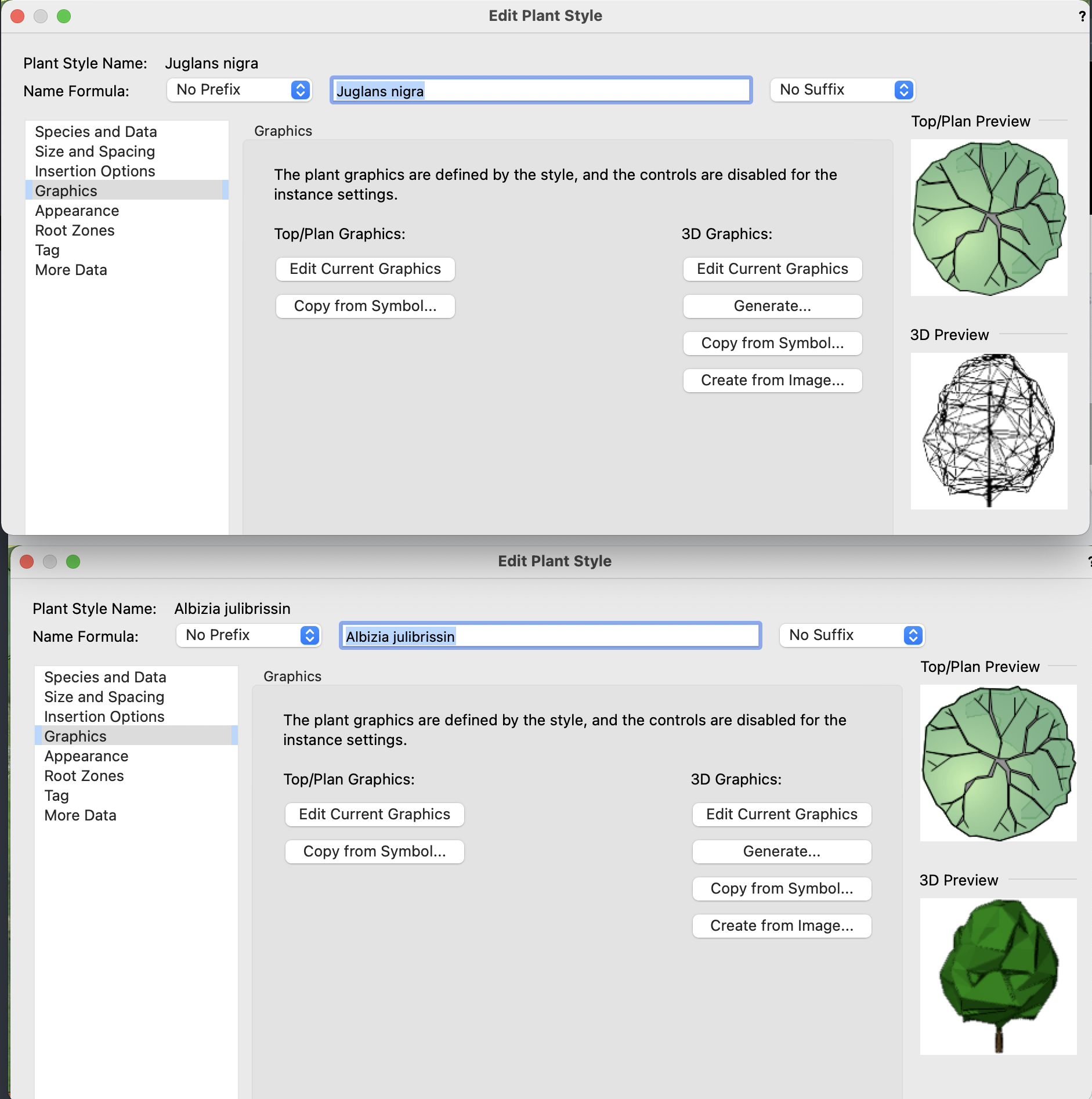
Hi, I was wondering if anyone could tell me what's going on. I'm using the plant tool, adding some new plants as I go.. and having no trouble using "Generate" in the Edit Plant Style > Graphics > 3D Graphics to create some models for the trees. ..until suddenly they no longer appear as normal shaded models, but instead only as wireframe. All the options (volume, shell etc are affected). I have no idea why. I didn't change any graphics/render settings. Now every time I go to set that, they only show as wireframes. I can view the previous ones I did as shaded models, but if I go to edit them they will only give me wireframe, so I have to cancel to back out. I can't see any 'setting' that makes them appear differently, and I tried closing and restarting to no avail. Has anyone had this before?

-
Hello Every Body, I am wondering if there can be any way to draw such an object with marrionette. just the guidlines would be also enough, maybe we can do a brainstorming. 3d - körper -.vwx
-
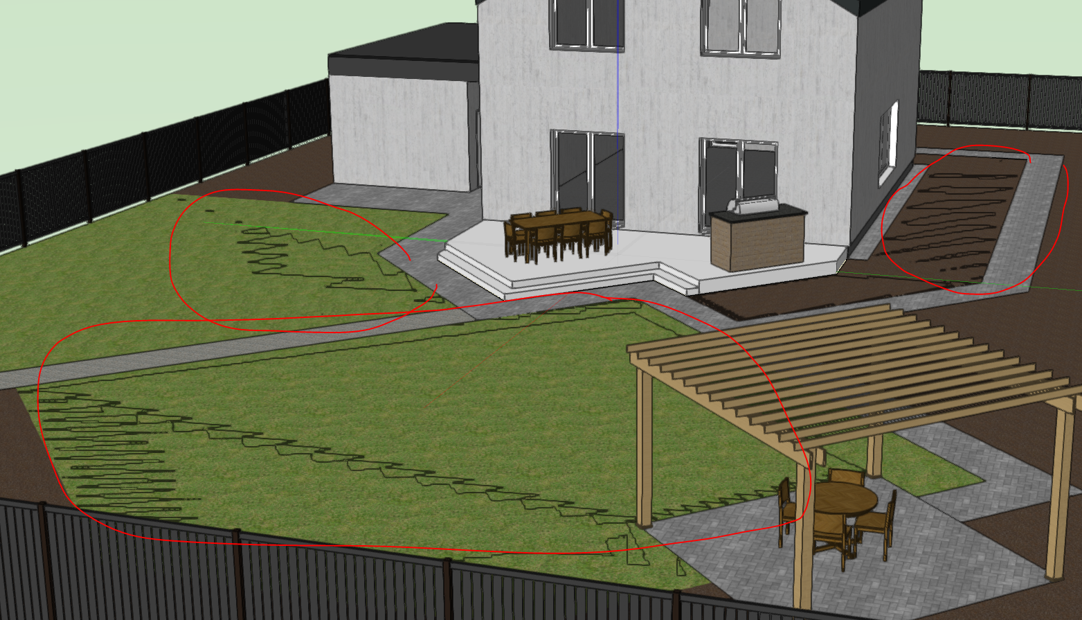
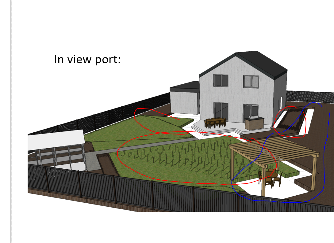
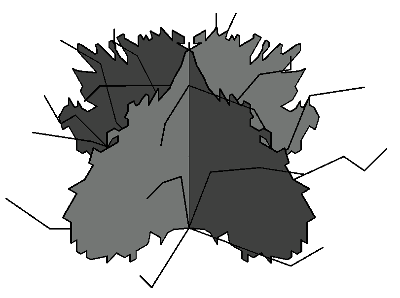
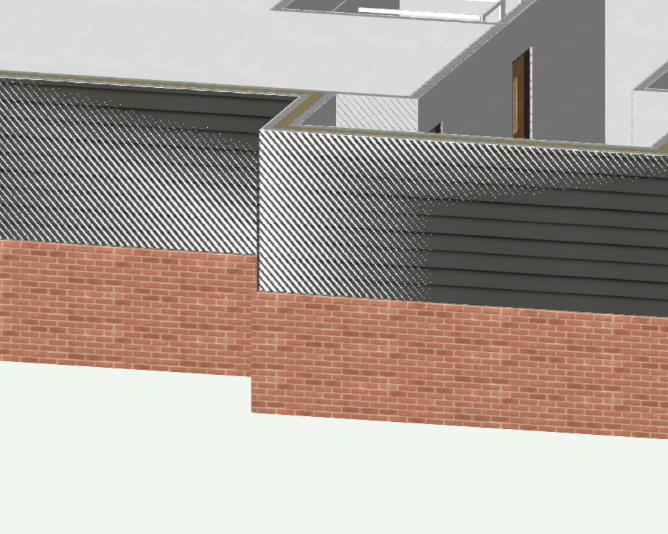
Hi, may be someone knows a reason why landscape area surface in 3D view flickers? When I move a view in 3D these black flickering spots getting bigger or smaller. They are also visible in view port. See pictures below. Previously I thought my PC was too weak, but recently I started using PC with recommended system requirements. Still the same. Site model is just around origin, no objects far from it. I noted also that this happens not to all areas, but I can not find a difference what may cause it. Any thoughts and recommendations here? 🙂 One more problem just appeared 🙂 Hardscape object (walkway) disappeared in viewport when I was creating it to illustrate flickering problem, see picture below. A class and a layer where walkway belongs are set to visible in viewport. Any thoughts why it disappears?


-
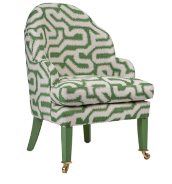
Hi, I am struggling designing this armchair -not the legs or cushion but mainly the back and side. Does someone has a way of doing this efficiently? For the cushion I would use subdivision to create the plumpness but for the back, I am totally stuck as there is this curved shape that goes up in the middle. Any tips would be appreciated! Thanks
-
Hi all ! Little practical question, do you know how is it possible to use the wall projection tool on a roof profile. I'm not talking about skylight or dormer but about the wall projection tool (in my case to show the modulations and variations of steel sheet that make up the roof on the 3D). Thanks you for your help !
-
 Hi all, Having a very frustrating time trying to rotate a 3D object off the working plane. When I watch the video on the tool from the Help site, the protractor icon automatically flips to match whatever face the cursor is hovering over, but it won't flip to match faces in my VW. I've tried looking for snapping options that might be disabled, but I found nothing. I even reset snapping just to be sure, the problem persists. I've tried restarting VW, the computer, a new document, modifier keys, but nothing changes.
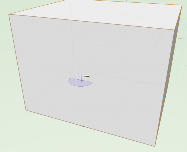
-

My Vectorworks Somehow Switched to 3D mode and I Can't Go Back
Stevenkgoff posted a question in Troubleshooting
I'm a scenic designer and was working on my drafting. All of the sudden, my design layer starts running extremely slow and has a blue tinge to it. It seems like my design layer switched over to 3D on it's own. I need to get it back to 2D so I can continue working, but I don't know how. I cannot find how to switch back. -
Sometimes objects become unsnappable. As in, their key points are not detected by the tool I am using to edit another object. In the attached video I edit a solid and try to adjust an extrude to snap to another solid object on the layer below. As you can see from the attached video, none of the points on this solid subtraction object are detected by the snap tool, but other solid objects on the same layer are detected. I think this must be a bug, I've noticed it several times in many different projects and versions of vectorworks over the years. The only thing I can think is that there is some way to make objects invisible to the snap tool. Its quite an irritating bug as I really disrupts my train of thought trying to come up with a workaround. Also, if I am working inside an Auto Hybrid object I cannot snap to objects outside of the hybrid object group when in a 3D view, I think this also must be a bug. Screen Recording 2021-04-26 at 15.05.40.mov
-
hey guys, so i just got my hands on a 2013 Mac Pro(12-Core Intel Xeon, 2 FirePro D700 6 GB, and 64gb of ram) and my 2018 baseline macbook pro seems to out perform it... is there anyone still using a 2013 mac pro. Has VW just moved past hardware from 2013? i can never remember what part of the system VW uses the most. Does it help that the mac pro has 2 graphics cards? does the 12 core Xeon help or hurt it? does VW2020 prefer clock speed over core count? my main workflow is Spotlight and occasionally OpenGL/renderworks. thanks guys.
-
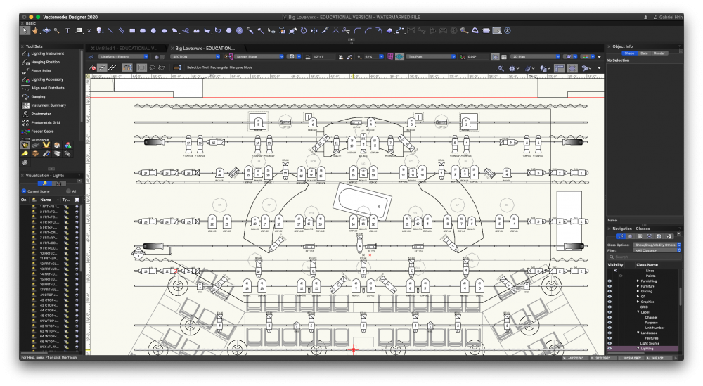
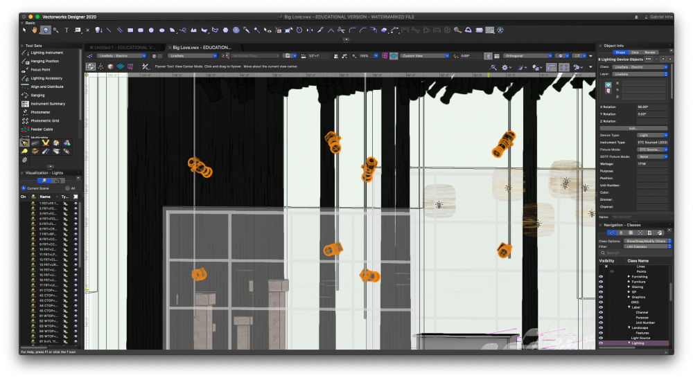
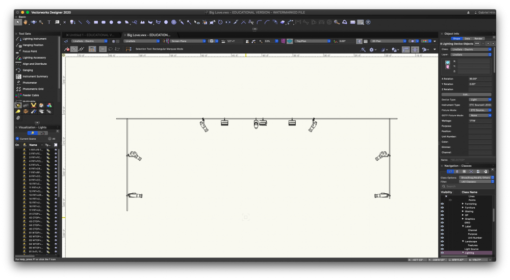
Hello Vworks World! Hope everyone is doing well in Covid times! The Vectorworks University programs have been amazing to check out during our mandatory home time. So, I am struggling with with a combination of Industry standard practices of having a "callout" style deck plot and drafting in 3D. In the show that I'm doing, I have 4 tail downs from 2 line sets at varying depths, and 2 Lustr Series 2 on each tail down. The goal was to render and test my beams in the plot, as well as create a 3d accurate version of the theatre, but my professor is now showing that what I need to do for clarity and data is create a deck plot using callout boxes in a separate design layer that shows *vertically* where they're being hung on the pipe, as well as all of the data that goes with each instrument (purpose, Channel, and Unit #). In my circumstances, I also have to be careful to not have 2 instruments representing the same data, because I'm using the Lightwright 6 Data exchange system. How on earth do I either A: create a movable section view of just the tail down and get the data properly transposed on it with text boxes. or B :have multiple symbols (2d and 3d) representing the same instrument, without repeating the data in the LW6 data. I really like having the 3d lights in the space, as I'm using a live section viewport for the whole drawing, and testing the beams was so helpful, I would hate to just delete it for a footprint. Please let me know if anyone knows anything about this, or if this is just wishful thinking! I've attached a few images to help! -Hrindous
-
Hi- Long time 2D drafter using some of my free time to dip my toes in the 3D world. I've modeled a simple wooden desk lamp in Vectorworks and I'm pretty happy with how that went. Now it is time to make the construction drawings and I want to see what the best practice is before I get some bad habits. My lamp is made up of two parts 4X Uprights and 8X Cross Pieces. I'd like to have a sheet for the Upright and a sheet for the Cross Piece. Each piece would need a top, front and right side view. My current solution is to put a copy of each piece on it's own layer and move the viewport crop around as I change the view. Am I missing an easier approach? I'd love to be able to click on the part in the design layer and have a command give me an orthographic projection of it on a sheet layer I can than annotate with dimensions. Any thoughts?