
Theo D
-
Posts
16 -
Joined
-
Last visited
-
Hi all ! I'm looking for a solution to my problem. Indeed, when (for example) I create a structural element and drill into it, it becomes a subtracted volume. So far, so normal, I'm thinking of using subtraction and editing either my hole or my structural element. However, it becomes a wireframe in plan view. Is it possible to keep the representation of my structural element, while having transformed it into a subtracted volume with the hole, so that my structural plan remains legible and not wired? Thank you for your answers
-
Thank you for your reply. I'm placing my dimensions correctly in relation to my section but they don't appear in the viewports. This would be very useful to me, not in perspective but in orthogonal section to avoid drawing it in 2D afterwards when it exists in 3D. Thank you
-
Hello everyone, When I make a section or an elevation with the clip cube to send as a viewport in a presentation board and I make dimensions of my section or elevation directly in my drawing layer, the dimensions don't appear in the viewport and I end up having to dimension my sections or elevations directly in the viewport. Is there a solution? Thanks for your help!
-
Hi all ! When I create a structural member, sometimes its position is locked and I can't copy it or move its location. Can you help? Thanks
-
Hi all, I want to insert a porthole on a roof but cannot find a porthole in the VW library. Does anyone have a solution? Thanks !
-
Hi all ! I would like to drill the structural member and framing member 3D profiles without VW transforming them for me into solid subtraction but although it keeps them for me as a structural member or framing member once they are drilled. If you have any solutions, I'll take them with pleasure! Thank you all
-
I think I found a way around the problem. Using mapping and texture coordinates I can make Blender understand that it is one and the same object
- 4 replies
-
- 1
-

-
- vectorworks
- blender
- (and 3 more)
-
Thx for your answer ! I export in FBX or in COLLADA but the problem is that Blender splits the geometric shapes for me, which is complicated for UV or texturing. For example, on a basic floor slat (extruded rectangular parallelepiped or created with slab), Blender imports it with many more edges (transverse in this case) than the twelve that make up the object in VWX
-
Hi all ! I am looking for the best solution to export my vectorworks project to blender for texturing and rendering. That is to say the best compatibility, the best format, the best way to have a blender project organized from vectorworks. Thank you all
-
Hi all, I have a problem with my export from VWX to Artlantis. When in Artlantis I apply my 3D grass texture, the texture applies but in the inner faces of my terrain. I conclude that my faces are upside down in VWX, except that it is not, my ground is indeed in the good direction. How to do? Thanks very much !
-
Hi all, Do you have a solution to "cut" the Artlantis file from Vectorworks? I have multiple floors across multiple layers but Artlantis considers that I only have one. I'm not talking about shaders but about layers. I specify that when I import from Archicad to Artlantis, Artlantis breaks down the project for me as it is in Archicad. thank you
-
Hi all, After creating my wall projection, is it possible to save my new wall profile as wall and use it again or do i have to redo my wall projection every time ? Thx
-
Hi all ! Little practical question, do you know how is it possible to use the wall projection tool on a roof profile. I'm not talking about skylight or dormer but about the wall projection tool (in my case to show the modulations and variations of steel sheet that make up the roof on the 3D). Thanks you for your help !
-
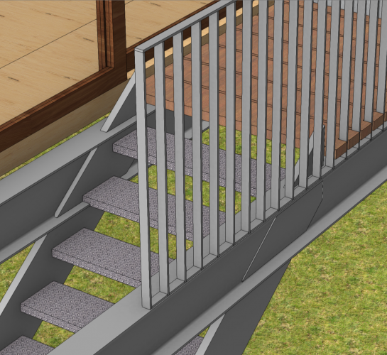
Hi all ! I want to connect the stringers of the stair under the beams while keeping the steps between each beam. How should I do it ? Thank you for your answers 🙂
-
Hi all ! I would like to switch my 3d archicad model to VW with IFC format. It works but once in VW the software does not recognize my BIM profiles of beams, columns etc, only as IFC entity. Does anyone have a solution so that the IFC profile can be edited and recognize ? (I would point out that in the other direction, from VW to Archicad, Archicad recognizes VW profiles ...) I don't know how to configure the archicad export so that VW recognizes my BIM profiles (I think the problem comes from there) Thanks !