


CipesDesign
-
Posts
5,153 -
Joined
-
Last visited
Content Type
Profiles
Forums
Events
Articles
Marionette
Store
Everything posted by CipesDesign
-
Joist and Hanger Symbols in resource manager?
CipesDesign replied to hollister design Studio's topic in General Discussion
As far as I know the only joist hangers included in VW's are part of the Framing Member Plug In and only for Top/Plan View. For details (front and side views) I go the the Simpson site and download their .dwg files, then import (into a separate file!) and clean them up. Over the years I have amassed a fairly large collection of the most commonly used ones which I keep up to date in their own VW's document (you could also use this document as a resource, making it browsable in all documents). As for nails, it's easy to draw one and use it. Depending on the scale, two lines in a "T" shape might be adequate. You could also maybe use the "Screw" with no threads. -
create a TUNNEL through the site model
CipesDesign replied to yasin2ray's question in Troubleshooting
If you only need a visual, what not just make the tunnel entrance black, or very dark, using a 3d polygon? -
Rendering directly on the design layer
CipesDesign replied to scottmoore's question in Troubleshooting
FWIW I use Open GL with Textures and Shadows for this type of quick look rendering. Works fine - no complaints. -
Could it be that your default setting in the Attributes palette is that arrowhead? Just a guess. And of course this shouldn't apply to a Railing (or other) object, only to lines. So if that's the case I would call it a bug. If it's something else, then hmmm...???
-
This is easy in VW's as well. 1) Add a Heliodon Object (AKA sun) to one of your Design Layers. Make sure that the settings are correct as to Lat/Long, Month/Day/Time, etc. 2) Then in Open GL (and other some rendering modes, if you have RW) shadows will be generated. 2a) Make sure that you go to View>Rendering>Open GL Options and check the "Use Shadows" option. You might also want to change the quality (of both the rendering and the shadows) from the "Low" setting (which is the default) to a higher setting.
-
20 Plus yers ago I used a dot matrix printer. I printed multiple, tiled sheets, cut off margins with an exact-o knife and taped them together. Then I brought them to a local copy shop and they made blue prints from them. Not really fun. And these days not necessary. Here are a couple options: 1) Buy a reasonable cost ink jet printer. Around 1,000 for D size and roll feed. 2) Send PDF's to your local architectural print shop and have them print. In my town it is about 1.25 per D size sheet.
-
You don't specify which Render Mode you are using. If it's Open GL check [View>Rendering>Open GL Options] to verify that "Use Shadows" is ON. FWIW, the default state for a new document is OFF...
-
imported DWG with colour lines ----> B&W?
CipesDesign replied to DSmith2300's topic in General Discussion
Usually the colors are inherited from AutoCad Layers, which are translated to VW's Classes during the Import process. If you select any of the colored objects it will probably have a little swoop-y "By Class" arrow showing in the Attributes Palette. The easiest/fastest way to change colors to black is to Select the objects ("Select All") and then: 1) Change the Line Color to black in the Attributes Palette. 2) *Sometimes* also might want to use the little dropdown menu at the bottom of the Attributes Palette to "Remove By Class Settings". Do not actually change the Class of any of the Objects. These are useful to sort out visibilities, etc. Another note: It is usually advised that all the objects from an Imported DWG File reside on their own discreet Design Layer. All of the tracing or whatever you will do later should happen on a new Design Layer. And you can Copy and Paste In Place from the Import Layer to any other Layer, thereby keeping the original imported date intact/unaltered (except perhaps the line color). -
Cannot create site model from 3D polylines
CipesDesign replied to Daisy Z's question in Troubleshooting
Sometimes you get good 3d data from a survey. Sometimes you even get a Site Model. But not usually. In that case, see below... There are a few steps in this process. To ensure success I have learned the hard way to: 1) Start with 2d Polygons. Make sure to verify that each (2d) contour is a continuous Polygon. Data from surveys is notoriously bad at this. I generally go through and visually/manually check each and every contour. I make sure that any unconnected segments are exactly coincident at their respective ends and use the Compose command to merge/join them. Also important that there are no "loops" or overlapping double backs. This will mess up a Site Model. I sometimes find it faster to trace over (in a new Design Layer) the contours on a survey (realizing that EXACT tracing is not actually possible, I accept that this introduces small errors, which in general do not amount to more than 3 or 4" which is within my tolerable limit; can be solved at the site IRL). Sometimes you need to trace anyway, if for example all you have is a PDF... 2) Select all of the (verified!) 2d Polygons and Copy. Create a new Design Layer and Paste In Place, thereby preserving the original data, and aligning the new copies with it. 3) In the new Layer, select all the 2d Polygons and run command "Modify>Convert to 3d Polygons". 4) Select one 3d polygon at a time and assign a Z value to it (note there is a somewhat automated way to do this, but unless your original polygons were created in the EXACT order - lower to higher or visa versa- this procedure can get royally cocked up - See command "AEC>2d Polys to 3d Source Data") 5) Double check step 4. No really! 6) Optional, but highly advised: Select the 3d Polygons and run "AEC>Terrain>Simplify 3d Polys". Use a reasonable number, eg: 24". This command will result in a Group of 3d Polygons. You can and should visually compare these to their unsimplified parents. If they are not too divergent they should be fine. Again, this does introduce a bit of slop. But in lowering the vertex count in each polygon your Site Model will behave astoundingly better later on. (You can also compare the vertex count in any of the parent/offspring polys. This is telling!) 7) Usually on another new Design Layer, Paste In Place the group of simplified 3d Polygons. Ungroup them. 😎Select all the simplified 3d Polygons and run command "AEC>Terrain>Site Model from Source Data" Depending on the size and complexity of the site this process can be time consuming. But in my opinion it's worth every minute (or hour!) in the long run. Now you have a Site Model. Perhaps later I'll write another how-to on all the awesome things you can do with it. -
Organizing scales for design layers and sheet layers
CipesDesign replied to rlb's topic in Architecture
Hey Joe, I could get really long-winded here, but I'll try to be concise. Before Viewports and Sheet Layers we used a method similar to the one you describe (also, making extensive use of Saved Views). This method is still a valid approach, however... Upon the introduction of VP's and Sheet Layers I felt somewhat forced to convert to VW's new, "preferred" workflow, using Design Layers for Model Data and Viewports on Sheet Layers for all other info (dimensions, notes, annotations). There is more than one way to skin a Vectorworks cat. Do I really like the "new" (circa 2009) workflow? Not really very much. But I use it anyway. Like drinking the Koolaid. I got used to the redundancies and the need to navigate in and out of a bunch of different "environments". It's actually all pretty confusing IMO. But one can get used to anything... In any case, I am still a big WYSIWYG advocate, and so I generally create Model data in 1/4" scale, which is almost always my presentation/output scale. One sort of good by product to the "new" workflow is that it somewhat forces me to separate my process into two distinct parts: 1) I get the graphics right (for me this excludes all annotations). This is helpful because in my experience builders mostly relate to pictorial representations, and don't generally like to read; and 2) I add annotations, so when they ask dumb questions I can say (eg) "Look at note 17 on sheet 4. See what it's pointing to?" P -
2021 make all attributes per class
CipesDesign replied to Christian Fekete's question in Troubleshooting
*Sometimes* I have found instances where VW's needs to be *forced* to comply. To do this I choose "remove class attributes" then choose "attributes by class". Also, I believe this drop down menu is in Attributes Palette (as opposed to OIP). -
Question 1) You could use a Crop that just barely covers the line. Ideally I would want to know what that line is and put it in and invisible class. It could be a Section Line? Note: FWIW I was alway taught that ground/grade lines are desirable in elevations... Question 2) Unfortunately Image Props are not real plants (LOL). You could try a couple things: Move it; make it invisible for that view; make narrower by scaling just the width, or you could maybe even draw over it in annotations with a polygon filled with the brick image...
-
Organizing scales for design layers and sheet layers
CipesDesign replied to rlb's topic in Architecture
I third that WYSIWYG approach. For architectural drawings I always use 1/4" for Design Layers. From there it's easy to scale up Viewports to 1" (for details eg) or down to 1/8" or less (for Site Plans). -
switching to black and white for construction drawings
CipesDesign replied to richardavatar's topic in General Discussion
There is an even easier way. Print to PDF, then re-save the PDF and add Grayscale Filter. This works perfectly, with one caveat: certain colors (yellow, eg) become much darker than expecting in Grayscale. So you need to do a bit of trial and error in that regard. -
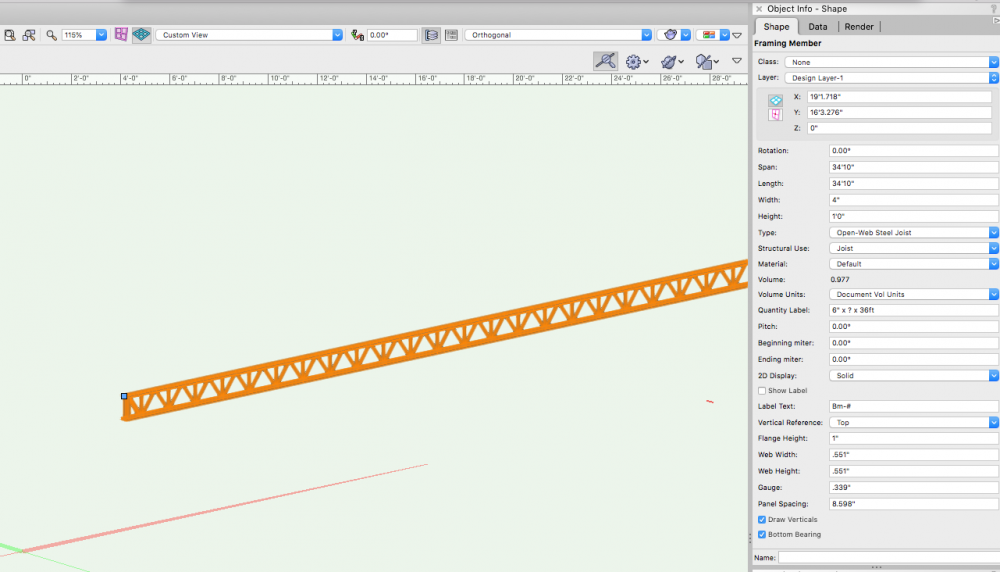
It's easy. Use the Framing Member set to Open Web Steel Joist.
-
Well in my experience you cannot un-stir it. See this recent thread. It's long and complex but well worth a read...
-
There is only one reason I can think of. One (or all) the tool(s) were deemed inadequate so they decided to create an new one to deal with it. Turns out the new one is also inadequate. It's like if you were to throw a bunch of random herbs in a soup pot, hoping to make it taste better. And it doesn't. So you throw in some more.... etc.
-
This may not be entirely relevant to the original question, but.... For my work (one-man shop, mostly custom residential one-offs) I always like to stick with a) what is the simplest way to get there, and b) how does the thing actually get built. So for a typical sloping garage slab I have always found that a Roof Face is by far the easiest and most effective tool in the toolkit. Set slope to 1/4" per foot and set the high point correctly as it relates to the adjacent floor and voila.
-
Filter views with different objects
CipesDesign replied to MartinBlomberg's topic in General Discussion
In terms of Visibility (which I think is what you're after) there are two ways to do this in VW's: either By Class, or By (Design) Layer. It all comes down to how you organize (or perhaps re-organize) your file. For instance, there is no reason that all "Hoists" can't be in their on discreet Layer... In terms of Selection (which can also be very useful), try using Custom Selection. For example, I often find that a s project progresses I need to segregate out certain objects. So I use Custom Selection to select all Red Objects, or all of a certain Class (eg) and then I can place all those objects onto a new Layer, or move them all or change them all. There is nothing sacrosanct about Design Layers in terms of how one chooses to use them. You just need to be aware about their "Z" height and stacking order. -
Try negative numbers?
-
John, in case you are not aware, check out the Workspace Editor. This is where you can find and add many many tools and commands. You can also create your own custom workspace (recommended!) and then add tools and commands to various places. You might be pleasantly surprised at what you find.
-
John, I have the Designer package and there are indeed a lot of tree and plant symbols, 2d and 3d, included. I am not certain of what is included in Architect package. Perhaps they are hiding, or perhaps you will need to upgrade. I recommend that you contact your sales rep and ask.
-
Is it possible that the Walls and Roof are on the same Design Layer? If so, try separating them and re-run the Fit To command. If not then maybe manual reshape is the expedient option.
-
Warning: Rant ahead (apologies in advance) My 2¢: Many of the inconsistencies spoken of here have become baked in to how VW is developed and programmed. In a mad rush to crank out new tools and features a lot of seemingly small (but very important!) things are overlooked. My sense as a very long time user is that this really started to get bad around ten years ago. The software started out (as "MiniCad") as a brilliant and elegant piece of programming which was easily managed, once understood. It has become (as VW's) a somewhat haphazard patchwork of add-ons and sometimes entirely conflicting pieces of code that is nearly impossible for a new user (or even a veteran user) to grasp. At this point the only useful thing to is FILE BUG REPORTS. Be as specific as you can about the steps involved. Point out problems and issues but don't try to solve them (the engineers are generally not receptive to our solutions, unfortunately). As a result of this, and as I mentioned earlier, I have tried but abandoned many of the newer "features" and gone back to older ("legacy") tools and methods. Fortunately for me I am a one-man shop and I have no need for BIM* compatibility (one-off custom residential practice, mainly). * Note: obviously BIM has enormous potential in all areas of design, architecture and engineering. I am not dismissing the potential and I understand the power that can be gained by its universal use, especially in respect the entire life-cycle of a building or buildings. However, from what I have seen it's just not ready for prime time, at least for me... End of rant -
-
Maybe because the Object is a Slab? (I don't use Slabs, I always use Roof or Roof Face. So not 100% certain.) One other method, but it'a PITA: Duplicate the Texture then mess around with the angle of orientation of the image. FWIW, I believe Slabs were introduced a few years back for BIM compatibility. Roofs and Roof Faces are older gen objects. But they still work fine in most situations.

