CipesDesign
-
Posts
5,153 -
Joined
-
Last visited
Content Type
Profiles
Forums
Events
Articles
Marionette
Store
Everything posted by CipesDesign
-
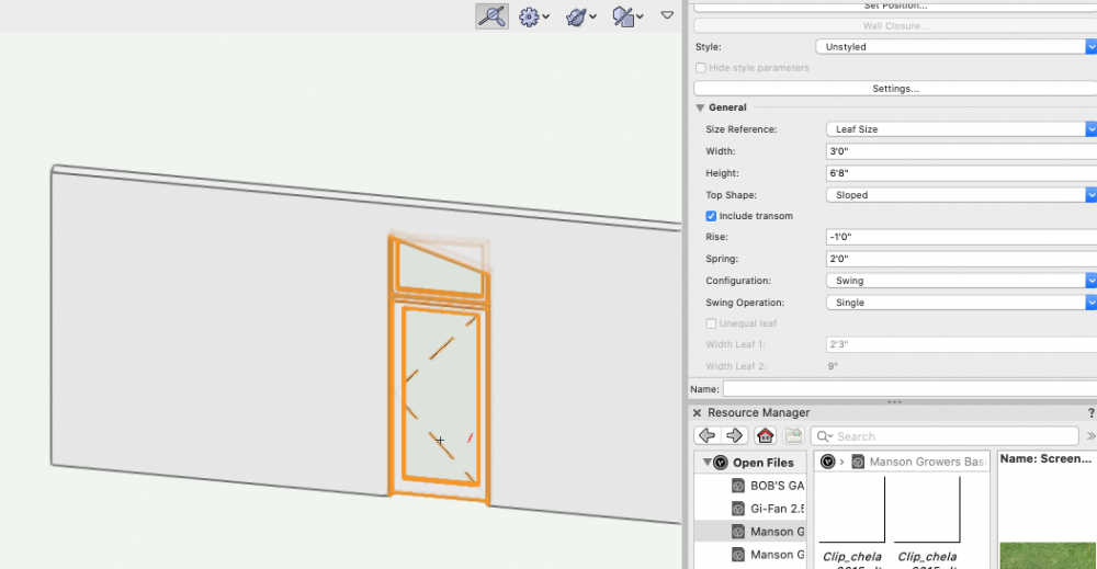
See attached... (negative numbers DO work) [This produced using VW 2022]
-
Yes they can. But not in this case. If a metal cap is what you want, this particular EAP is an easy-peasy no brainer.😜
-
See attached. To make an EAP (extrude along path) first draw the profile, then draw the path, then select both objects and select the command Model>Extrude Along Path. You then select the path object and voila. One note, you almost always need to Edit the Profile after creation in order to get it aligned as desired. In the attached image, the cap is an EAP. This took me less time to create and adjust than it took to write this reply 😉 I always advise that you create a discreet Class for the Cap, then way you can easily choose to have it show or not in various views and viewports.
-
The Extrude Along Path command would be a good fit for this task. It's pretty easy to do and will give you what you need for model (visual) and for details (sections).
-
Change Texture of Floor in different styles
CipesDesign replied to JochenDerAllvater's topic in Architecture
Generally I use the method that most closely resembles real life, just like Tom says. (US/Imperial units): cover the entire area with 3/4" thick Floor Object for the structural floor sheathing and then create various additional 3/4" thick Floor Objects for each room or series of rooms with same floor finish. -
There are two types of Objects that I always insert into Walls: Doors and Windows. All other Objects I do not insert: Plumbing Fixtures, Cabinets, Appliances...
-
It was waaaaay back, at one of Janis Kent's (anyone remember her?) MiniCad Training Seminars, that's when I "got it". That was the best three days (of classes) that I ever spent in my life. And most of what she taught us is still relevant today. Even though VW's has changed (and not always for the better - today I'm very upset about the "new" orbit animation tool eg) the basic bones are still the same.
-
I would agree (but maybe reduce it to 7-8 times, once one is really proficient). But there is another important point here: what about the time saved at the other end, in producing Elevations and Sections? And the amazing visual presentations possible without the need of hiring a watercolorist?
-
How do I model a Saltbox Roof (Asymmetric gable)?
CipesDesign replied to MaltbyDesign's topic in Architecture
A note regarding Stories... I never use them! IMO they only made the whole user experience more confusing. That said, I *think* (someone could correct me or verify) that Stories were added to facilitate BIM/ICF capabilities. As a small one-person operation specializing in one-off residential design I don't need those capabilities. Also, IMO all the "automated" drawing/file setup tools are dangerous as they prevent the user from learning the basics of Layers and Classes and how to set up a file manually, which is really easy in most cases. Again speaking from my experience and needs. Large projects with multiple users are a different story (pun??). -
How do I model a Saltbox Roof (Asymmetric gable)?
CipesDesign replied to MaltbyDesign's topic in Architecture
Old School: Start with Create Roof(s) then Ungroup which will produce various Roof Faces. These can be easily Clipped/Added... -
Create a Section Viewport. Measure there...
-
Well, in the old days when I was building a lot, the very nice and knowledgeable people at the lumber yard did takes-offs from plans, for free... Additionally, for old-style 16" O.C. Wall Framing, we used to use 1 stud per foot, which was always a remarkably close estimate and accounted for kings and trimmers at openings and corner studs, etc. The length of the plates is easy, it's the perimeter times 3, etc. etc. Maybe you should make a bit of effort with math?? It's really not that hard. But in my mind it really comes down to a fundamental dichotomy: some people understand ALGEBRAIC type math, while others hate algebra and understand GEOMETRIC type math better. I am of the latter school, being quite a visual thinker. But you can use either one to solve the same problem(s), and even cooler, you can use one to prove the other 😉 For me the teachers I had, with one notably exception, could never get me to understand. So there's that as well...
-
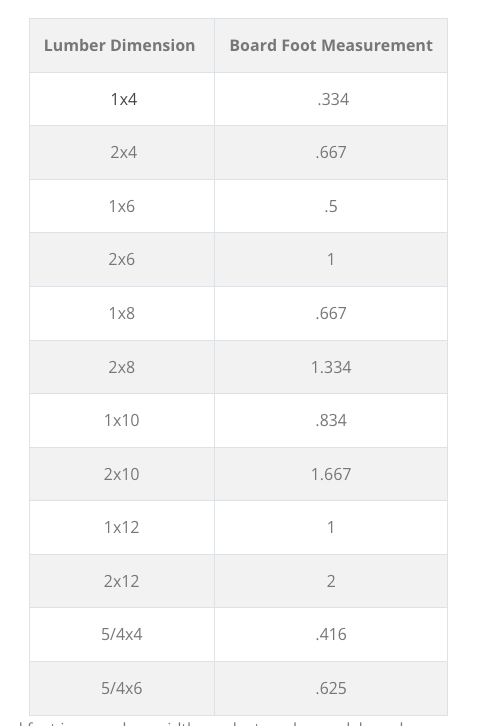
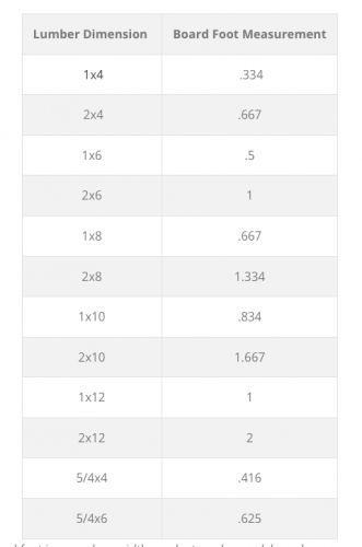
You could probably do this in a fairly simple spread sheet. The math is pretty simple. Using the attached table, all you would need to know is the total lineal footage of each size of lumber...
-
I have complained and filed bugs regarding these issues... No joy yet. Maybe someday?
-
How would I create detailed brickwork for the facade of a building?
CipesDesign replied to Ami's topic in General Discussion
One way I have cheated/fudged the Wall Features won't-go-to-corner flaw is to let them go as far as they can and then create a 3d Object for the corner(s)... Not perfect, but mostly workable. -
landscape area not aligning on site model surface
CipesDesign replied to tristanwel21's question in Troubleshooting
Assuming the your Plants and Site Model are on the same Design Layer, Select Plants (or almost any other 3d Object) and then AEC*>Terrain>Send to Surface (* It may be that this command is in a different Menu Column in the Landmark Workspace). You can also adjust manually by typing in a value in the "Z" or Elevation field in the Object Info Palette. -
How would I create detailed brickwork for the facade of a building?
CipesDesign replied to Ami's topic in General Discussion
The only issue I have with Wall Features is that after many versions and many bugs filed, they still will not go all the way to the corner of the wall. For me this has been and will always be a deal breaker...- 11 replies
-
- 2
-

-
- architecture
- walls
- (and 3 more)
-
How would I create detailed brickwork for the facade of a building?
CipesDesign replied to Ami's topic in General Discussion
You're welcome. PS: Chamfering or easing the edges of the stone and making each block "lumpy" would add more realism. This is possible but requires more 3d modeling prowess than I usually need. If you need that, I'm sure others can help.- 11 replies
-
- 1
-
-
- architecture
- walls
- (and 3 more)
-
How would I create detailed brickwork for the facade of a building?
CipesDesign replied to Ami's topic in General Discussion
Not sure you need to attach to walls. I would probably just drag into place such that the extrusions just barely sit proud of wall exteriors. I would therefore make the extruded depth slightly less than the thickness of the walls. I would also create a new discreet Class and put all the extrusions in there. That way you can make them visible/invisible in various views. Maybe invisible in Top/Plan and visible in Elevations?- 11 replies
-
- 1
-
-
- architecture
- walls
- (and 3 more)
-
How would I create detailed brickwork for the facade of a building?
CipesDesign replied to Ami's topic in General Discussion
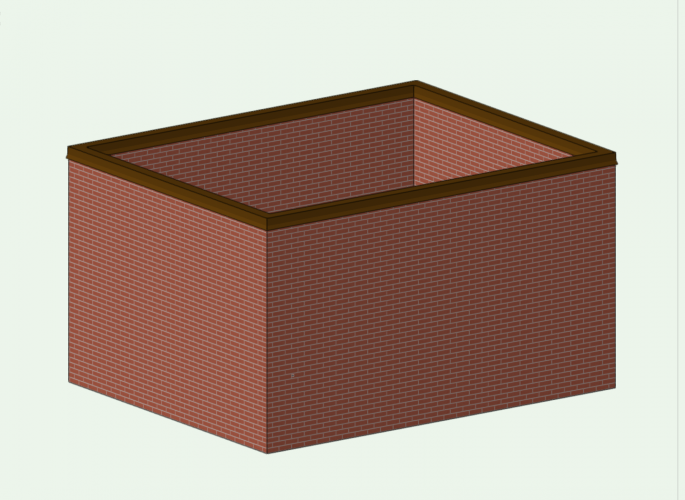
I don't think you can do this using Walls or any "built-in" tool in VW's... But you can easily draw or model it Depends on whether you want/need 2d or 3d, but for both I would start by actually drawing the pattern. Because of how VW's is organized I would recommend doing this in each frontal view (not in plan view) which will help when you get the the 3d portion, below. Draw each block as a closed polygon (Hint: you can initially draw all of them such that their edges align, then use the Offset Tool to create the grouted spaces). Now you have the 2d. For the 3d you can go a step further and Extrude the Polygons. Before doing so (or maybe even earlier, maybe this the first step if 3d is your goal) I would go toTop/Plan view and draw the footprint of the building for use in later steps.* (Hint: in VW's, if you select more than one shape and then Extrude, the result will be one single extrude which contains all of the shapes. This will be very helpful here I think. Note that you can always double click into an Extrude to get into the parent 2d shapes, for editing purposes; you can also use Ungroup, which will result in separating the shapes from each other) * Remember that when you extrude in VW's the extrusion is always created at 0/0. You will need to select and then group each discreet wall and then go to Top/Plan View and drag or move it so that it is properly aligned with the footprint. Do this carefully. By holding the Shift key it will constrain the drag to horizontal or vertical, which is enormously helpful. This will be a piece of cake for most of the facade(s), but I suspect you will need to be careful at the building corners. These might take a bit more thought, depending on how the blocks stack up (pun. haha). I suspect the the sides of each facade (wall) will have gaps that will then interlock with corresponding gaps on perpendicular walls. One thing I always keep in mind when modeling buildings in VW: Almost every material we use to build actual buildings can be described by very basic geometry. Nearly every piece of anything that goes into a structure is a simple extruded form. Think lumber, bricks, plywood, etc., etc. I always try to think ahead and determine the most elegant and efficient way to describe the 2d shape and in which plane it will be extruded. If you think like that this project will be a fairly easy exercise. [Note that for the columns VW's does have pre-made parametric objects you can use.] Let us know how it goes.- 11 replies
-
- 1
-
-
- architecture
- walls
- (and 3 more)
-
As a last resort, you could ungroup the scale bar. It will lose it parametric abilities but then you can add or modify your own text. And then regroup for management.
-
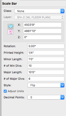
It *might* be the font. You can check by selecting the Scale Bar and then changing font (and/or size) in the Font menu. Yes they are editable, select it and look in the OIP where you find a variety of user input fields. See attached...
-
Congratulations on annoying features :)
CipesDesign replied to Kaare Baekgaard's topic in General Discussion
Haha! Right 😉 -
Agree with all of the above. For most single family residential sites I ask the surveyor to include extra area in the topographic data so that I can crop out the weird random anomalies at the edge(s).
-
Congratulations on annoying features :)
CipesDesign replied to Kaare Baekgaard's topic in General Discussion
Remember guys: Don't anthropomorphize your software. It hates it when you do that.