scottmoore
-
Posts
673 -
Joined
-
Last visited
6 Followers


-

Saved Views - classes turned off
scottmoore replied to James Dawson Design's topic in General Discussion
For any embedded classes created by symbols and PIOs that you use regularly, I suggest bringing them into your template file and get all of your visibilities set in saved views in advance. This way you can avoid tedious work while designing or drafting. You can always purge later if you desire. -
I have a pair of 35” curved and I love it. I have them set up somewhat asymmetrically. In other words, the bezel is not centered but instead off to my right. My main screen is just off center to my left so that is not uncomfortable at all. Currently I like having information split up on separate screens. That said, a 49” might be quite nice!
-
Video images are via textures. Add an image to the “color shader”. Apparently the plug automatically adds a glow attribute to any texture that’s used for video, but I always do that myself so I can adjust the overall brightness. I typically start at 125% and then look at results. as far as mapping is concerned, the plug in will default to scaling the image to the overall width, you can adjust scaling and position from there. Keep in mind, it will NOT asymmetrically scale. In your case, you have a wide format image, wider than 16:9 for instance. Ideally you would want either an image that is proportionally correct for your output screen ratio, just like you will have for actual event content. Alternately, you need a screen image that can scale up and not lose any important visual content. in your case, a really quick fix would be to import that image into your drawing, then create a square the same width of the image, center it on your image and move it to the back. The square should be made the same color as the existing background. (In the color attribute pallets use “custom color” and you will find an eye dropper that can sample the color you need for fill). Take a screen shot of the square. Now replace the color shader of your existing screen graphic and your black background will fill the top and bottom of the screen. Sounds like a lot to do, but should only take a minute.
-
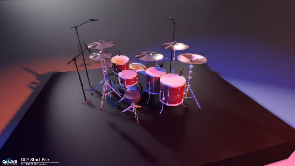
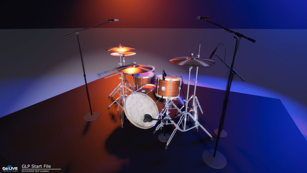
Thanks for the plug Grant! During the pandemic I started a new library of more detailed symbols since many users are rendering in other applications that are much quicker at processing higher polygon counts. Then the pandemic ended and I have been slammed, but at some point I will have them available. Here are a couple of images of a vintage style drum kit. These are VWX symbols that are textured in VWX and then rendered in Capture. At 4k the renders took less than 5 sec each. These are scaled back to upload.
-
That is the same thing I have been seeing. The process is exacerbated greatly when a user is on a slow internet connection. On a few occasions I have actually seen the temp file that VWX creates (.tmp perhaps? I don't recall), which really should only happen in the background from what I understand. I've stared at my dropbox folder and have seen it pop up for a split second and then disappear. On one occasion it popped up, replacing the .vwxp file and never left. That's how i figured out there was such a thing. Regardless, we seem to be moving along ok at this point. There are a lot of users on this file which also creates a bit of a challenge.
-
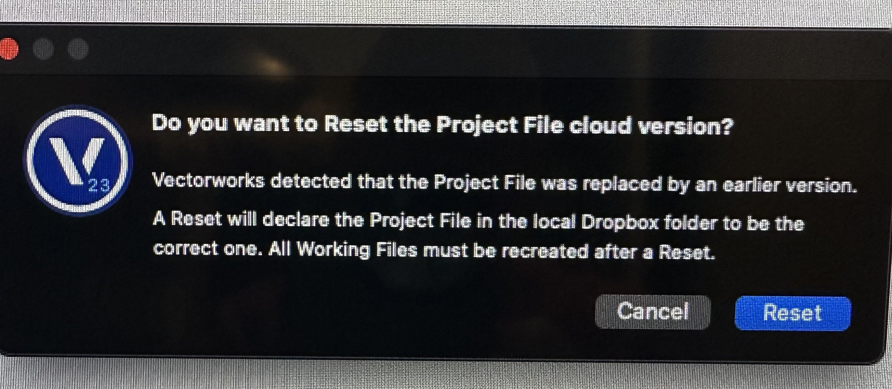
Rick, thanks. I can imagine that someone may have neglected to trash their working file after a reset and seeing an issue. That does make sense. What I don’t understand is what causes that in the first place. This particular project has been a bit of a hassle for some reason.
-
Pat, sorry for the confusion. “Working on a project file” meaning that we are using a project file. Everyone is indeed using their working files. I can imagine that someone has used an older working file once the project file was reset which can cause issues, just not sure how this happens in the first place.
-
I am working on a project file, shared on Dropbox and we have been getting the “reset the project file” notification. I have reset it, the lead administrator has reset it, and I am still getting this message. Any suggestions? I am guessing it is time to start using the cloud service for hosting.

-
Streamdeck integration.
scottmoore replied to Matster's question in Wishlist - Feature and Content Requests
Sweet -
Arena Model Available
scottmoore replied to scottmoore's topic in 3rd Party Services, Products and Events
Jake, thank you for the kind words. As to the suggestion, I love the idea of a completely parametric arena model, but I have no coding skills whatsoever save for manipulating some existing scripts to do very simple tasks. Maybe Andy Dunning and I can partner on something, but neither of us have any spare time! What I have done in the past for smaller arenas is turn off the 200 level, add a wall around the perimeter 100 level and lower the steel and ceiling. Takes a couple of minutes. -
He’s looking for Ribbon Lifts. I believe formerly Stardrive.
-
Streamdeck integration.
scottmoore replied to Matster's question in Wishlist - Feature and Content Requests
There are a ton of usable images of the Utah Teapot online. Does it have to be SVG on the Windows platform? I’ve used JPG and PNG almost exclusively on mine. (Mac OS) -
Speaker Array - Rigging Frames & Pull-Back Bar
scottmoore replied to Mark Aceto's topic in Entertainment
Agreed -
Speaker Array - Rigging Frames & Pull-Back Bar
scottmoore replied to Mark Aceto's topic in Entertainment
Understood. I am of the opinion that it’s better to rely on the manufacturer’s calculations than hope that the data entered into BraceWorks and the resulting calculation is correct. Any reputable audio vendor using major manufacturers equipment will utilize an application that calculates those weights specific to which hole is selected on the bumper, the particular angles of each cabinet and whether or not there is a tilt back bumper underneath. Most riggers and engineering firms would be more apt to look at these numbers I believe. I am just concerned that we open up a potentially huge can of liability worms when we try to make VWX be the end all be all of production work. I love the idea of it and am seriously impressed with your work and attention to detail (as always), but we all need to be careful. -
Speaker Array - Rigging Frames & Pull-Back Bar
scottmoore replied to Mark Aceto's topic in Entertainment
Great work as always guys. Quick question regarding weight calculations and your processes on projects: do you take the BraceWorks calculated weight and compare that to the manufacturers data provided by your audio vendor? To my way of thinking, one would be better served to input the data from the manufacturer than relying on BraceWorks, especially if the arrays are hanging from dedicated hoists and not attached, either by hoist or dead hung, to a truss structure. Just curious.