All Activity
- Past hour
-
 Good point it should be possible to make it. I'll try to make some test when I will have free time...
 -
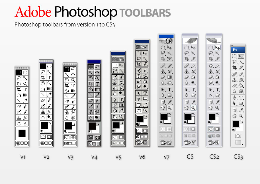
No comment: Source: https://www.deviantart.com/lukeroberts/ My favourites: I do not think, that icon changes are bad but in some cases they are not recognizable from the first site. The best is split tool evolution from scalpel to paintbrush, also small arrows which expresses movement they made sense...
-
Agreed. If you want a faithful representation of such a building + are not looking to add/remove/modify the geometry then this is the way to go, and an approach I've taken on one particular project. My experience is that if you are going to be combining existing + proposed architecture in the same model, adding/removing/modifying walls/doors/windows/floors/roofs + looking to produce separate 'as existing' + 'proposed' drawings, then it's preferable to do it all using Wall/Slab/Roof objects. I personally would not be modelling the existing architecture using 3D Solids unless I had a very good reason for doing so which in my case has only been one project so far. Remember, existing architecture is often just as complex as the new elements + involves multiple components: presumably you wouldn't advocate modelling these build-ups manually? Plus what about tagging + reporting on those objects? Analysing existing + proposed thermal performance etc? What about Top/Plan representation of the different objects? My point is that it's misleading + inaccurate to simply say 'solids are far better for existing conditions' but I think you've qualified that statement now + we're probably kind of in agreement, just coming at it from different positions/workflows.
- Today
-
I don't believe you can. You have more control over this kind of thing using Data Tags however. I assume you're talking about the built-in Plant Tag.
- 1 reply
-
- 1
-

-
 Hi Pat, sorry for the late answer. Here's a file created with VW2012 - that worksheets behave different than in the office.. Unfortunately neither column F nor J calculates correct - legacy issue? ok - here we go Column I lists the weight of steel. Column J shall calculate the volume of the several parts Column G shall calculate the weight of every part - and summarize in row 2 Column H, K and L - please ignore (just tests). Experienced to have the Length of the parts in different column (for 3D-channel and Extrudes) I have another column with IF((H2=0),J2,H2) to have all length values in a common column. There are more columns to calculate other things - so it's a bit more content at the end. So let's say I created the Box-worksheet working correctly - is it possible just to copy this worksheet, make some settings (where and how...) - in order to calculate the values of the parts in class "Rack" - in opposite to create the Rack-worksheet again from scratch? Inbetween I did it from scratch but keep curious if this can be done a 'smarter' way, y'know? Thanks, Peter test.vwx
 -
Is there a way to have a plant tag display on two lines? I have a tag that is a bit long and would fit better on two than one.
-
Depends on the subject matter...and how high you set your bar, I suppose, and what you consider acceptable as a base to coordinate your work against and what quality of drawing you want from the model. 15th century cottage with no vertical walls, and with huge deflection in floors and joists = 3D model. If the existing building is 'virtually' vertical and horizontal, I might consider walls and slabs but it is not necessary other than for expedience. An existing wall does not change, unless it is demolished, or rebuilt, or clad or lined, in which case the new bit is a 'wall object'. Existing bit does not need to be. It can remain a solid. There is less risk of it being modified inadvertently when a wall object updates.
-

macOS 14.4 Compatibility Issues with Vectorworks
Uri Ben-Or commented on JuanP's article in Tech Bulletins
Is it possible there are few triggers for those crashes? i'm using Strata 3D software and the crash is happening only when Strata is at the background. I also using an external display but when i disconnect it, the crashes continue. - Yesterday
-
Take a look at the Worksheet Function Reference. In VW2024 you can get just about any wall length you want. https://developer.vectorworks.net/index.php?title=Worksheet_Functions#Specialized_for_Wall The reference has documentation on how to use the following wall lengths. Length() Returns the length of a wall or its components. Length('control line avert core', [optional parameters]) Length('control line center', [optional parameters]) Length('control line facing core', [optional parameters]) Length('control line left', [optional parameters]) Length('control line right', [optional parameters]) Length('avert core gross', [optional parameters]) Length('avert core net', [optional parameters]) Length('center net', [optional parameters]) Length('facing core gross', [optional parameters]) Length('facing core net', [optional parameters]) Length('left gross', [optional parameters]) Length('left net', [optional parameters]) Length('right gross', [optional parameters]) Length('right net', [optional parameters]) Length('openings avert core', [optional parameters]) Length('openings center', [optional parameters]) Length('openings facing core', [optional parameters]) Length('openings left', [optional parameters]) Length('openings right', [optional parameters])
-

Create Label Legend from Lighting Device produces scrambled legend
klinzey replied to Tim Olson's question in Troubleshooting
Can you post a file? It's difficult to see what's happening just from screenshots. The only thing I did notice is that there is no instrument symbol shown it the layout. This would cause problems because the label legend uses the instrument symbol in the label legend to determine the relative locations of the labels. -
Clever, thanks
-
thanks for that - was inserting a door that wasn't preset in other locations but once in the curtain wall it was defined by the the preset. Appreciate it
-
Have you tried using pillar objects? Draw any polygon or polyline. AEC>Pillar… > give it a height. This helps with irregularly shaped walls. Regular wills will join to Pillars using the Wall Join tool.
-
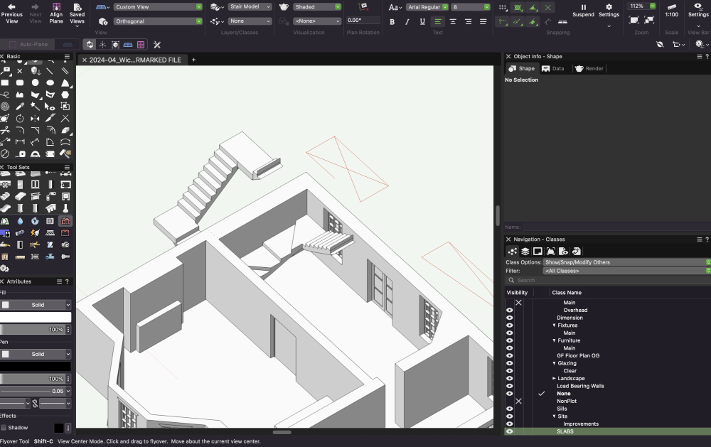
Hello - I am trying to come up with a U-Shaped cantilevered staircase in the below configuration but I want to avoid the stair being in front of the window. Is there a quick way of determining the geometry without having to play around with the settings several times over? Model attached. Note the final level (not shown in screenshot) is including the 'SLABS' classes - model attached if anyone wants to play around.2024-04_Wick House_MODEL.vwx 2024-04_Wick House_MODEL.vwx
-

Set Lighting Device Values
Jesse Cogswell replied to Pat Stanford's topic in Resource Share - Vectorscript
Some difficulty comes depending on which fields you are updating and which version of Vectorworks you are using. For instance, if you are trying to change the Symbol field of the Lighting Device and are using VW2021 or newer, you need to update both the 'Symbol Name' field as well as the 'Symbol Definition' field with the new symbol name. The other very important thing is to include a ResetObject command for the chosen Lighting Device after changing fields using SetRField so that the new values take to the Lighting Device. And also include an ApplyLightInfoRecord command if you are using a script to change Lighting Device instrument types. -
Interactive Sizing Insertion Mode for Doors/Windows (added in VW2023) is great in these circumstances because you can size the PIOs as you insert them, assuming you have a survey underlay you are tracing over or other guides you can click to.
-
Me too. On the other side I hate that in VW open 2D Elements like a curve can have a Fill !? The rest of Fill Attributes is all fine in VW. Microstation also had a Fill or "Is closed" object Setting. But Hatches were also separate extra elements like in ACAD, which was a PITA in 2D CAD times. Thankfully most of architects are now at a state where Hatches in Plans are generated from 3D BIM Models and appearance controlled by Viewport Styles, Class overwrite, and such things.
-
 Jack Mitchell joined the community
 -
You can select and edit multiple Windows via Window Settings or in OIP at a time. That is what we did before we had Styles. Yes, Styles are great. Styles are mainly to define the character of the Windows. E.g. one Style for your Wood Windows and another for your Metal Windows. To define Jamb dimensions, offsets, Material Classes, .... While overall Window dimensions, Sash configurations and such stuff will be unlocked in Style and edited selectively for each Window. However, at a certain complexity it may make sense to create more than one single Style for "Wood Windows". It has the disadvantage that when really something like a Jamb thickness has to be changed - you have to update 2 Styles. But you may have advantages to group other Settings and lock it to "by Style" and faster switch multiple "sub Style" Windows in one go.
-
Just checking as you have an M1: updating to Sonoma might help. To some of the users, that is… (see Compatibilty thread on the forum)
-
Right. In most graphics programs an object can have both an outline(pen in vectorworks) and a fill (fill in Vectorworks). In AutoCAD, if you want a fill, you use a separate object (hatch, super hatch, wipeout, really fat polyline, etc…), so you end up with two objects where most programs would only have one. I prefer the Vectorworks approach personally.
-
I used that for years. Even at times when my eyes were still good.
-
Interesting thoughts. The good thing for me is just that lately there came some movement in the non existing Speckle Connector. Means that so far it was known that a "community" tries to build a Connector but had problems and we never saw any early versions. Now there seems to be a real chance that Speckle stuff will maybe work on it. Maybe even with the help of VW stuff. Users of Revit, Rhino, Sketchup, Blender, Navisworks, PowerBI, QGIS, that other GIS, .... and even Archicad users are already heavily collaborating between each other with Speckle. But my only serious Software supported by Speckle ins Blender. (Beside that I start looking at QGIS or Unreal Engine) So the only thing I can do to test Speckle is uploading an IFC to stream it to Blender .... (Which doesn't need Speckle as you want BlenderBIM AddOn anyway) I need and want finally Speckle Connectors for my VW and my Bricscad.
-
I still have to arrange the palettes when I start up the program, but they stay put after the displays have gone to sleep and wake back up, so the bigger annoyance is resolved, thank you
-

Approaching the Wall Tool vs Solid Extrusions
VIRTUALENVIRONS replied to InchSw3's topic in Architecture
The Casing If there were lots of windows that were similar, but different sizes, I would create one window using Extrude Along Path (EAP). I would edit it so the path was the outside on the casing. Then all you have to do is increase the size of the Path. The Panes, The same could be done for the individual panes and they could be symbols. Then, just some basic math to recreate all the panes. I make this sound simpler than it is, if you have not done this before. But, this is how you learn. -
Isn't VW Fill basically the same as Color by Object/Layer/Block in ACAD ? Ah, ok, it's not a bout a VW Fill Color but Fill Type Hatch, Image, Mosaic, .... Beside it looks ACAD has also Layer or Object transparency. And if VW "Hardscapes" are 3D and use a Render Material (RW Textures), yes, a pity, VW does import DWG Materials fine. But unfortunately does not export VW Materials. (Often asked for that in the past)