


Minna
-
Posts
20 -
Joined
-
Last visited
-
Problem solved! Thanks to everyone who helped and special thanks to Tamsini for the video - it was a very clarifying package! The big issue with this was that the architect had sent me material made in the correct coordinate system and material where the coordinate system was wrong. So I didn't believe in my own knowledge and wasted my time before I realised what the problem was. Maybe this is a relatively new user problem... 😄 An interesting detail in the material I received was that the base material sent by the city also worked strangely when imported into Vectorworks. When it was brought to a base where there was no architect specified rotation angle everything went fine on top of each other. But, when you used the rotation angle then one of the files moved maybe about 3 meters to a different spot. Can you tell me what could be the cause of this? -Minna
-
Hi TeeMuki! You are from Finland?! Can I send you a message in finnish? _Minna
-
Thanks for your replies! I actually have the coordinate point. The architect has defined the x,y,z coordinate point. I'm trying to figure out if I can somehow import it into the georeferenced VW plan base. Poot: did I understand correctly that in your instructions the VW base is not georeferenced at all? I didn't quite understand how to do that...I wonder if there is a tutorial video for this? The problem seems to be only in these ArchiCAD files. The other designers files are geographically correct so I would then have to manually transfer the other designers plans (electrical, transport etc) And indeed importing ArchiCAD files as reference files is impossible And yes...I do have my user origin next to my site 🙂
-
Hi! How do you import Archicad dwg files to a referenced VW site model. My site model is in correct place in a world map but all Archicad files are bound to an internal origin so that the 0,0 point is given separate coordinates (by architect - it is in dwg file) Same with IFC files. Its really difficult to try to get them to the right place by dragging and it is impossible to use them as reference pictures. Some how i have this problem is specific to ArchiCad files. Is it just a drawing style, i.e. can I instruct the architect to create a different file that would go to the right place on the map? Has anyone else had a similar problem and how have you gotten such files to work as reference files? I'm a fairly new user so I don't know how to solve this problem and I couldn't find a similar article anywhere.
-
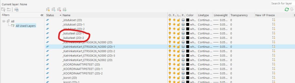
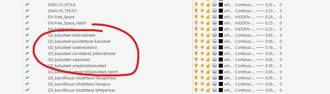
Follow-up question... Now I got all the sheet layers to show up as they should (hurray!), but the problem is the VW desing layers, which come into the dwg image multiple times. It seems that autocad compresses objects/lines/symbols of different VW class classification into one layer which is originally VW desing layer (i.e. I have VW desing layer kalusteet and class system GD_kalusteet-leikkivälineet, GD_kalusteet-ympäristökalusteetetc. and now these are all in the dwg on the kalusteet (2d) layer and when you explode that layer in autocad, the objects/symbols go back to the VW class layer (which also appear in that autocad layer list), but that furniture 2d layer cannot be removed. And there are as many of these furniture 2d layers as there are sheet layers where they appear in the work. My apologies for the slightly confusing post. I hope someone understood what I meant -Minna

-
Thank you so much Pat. I need to try this! -Minna
-
Am I really only one with this problem?
-
Hi! I need help from someone who can also use AutoCad. I have a client who wants the files in dwg format for archiving, but just a dwg exported from vectorworks is not enough, all sheet layers should appear in the dwg file as layouts (as if you had done the work in auto cad/archicad) I have sent the whole work in dwg format and the other pages in pdf format . So is there any way to send the sheet layers from vectorworks in dwg format or do I have to rebuild these pages in autocad as layouts with the same look as the sheet layers from vectorworks . It is not just one job but several kindergarten yards with 4-6 sheet layers in all . If there is a tutorial video on this, could you kindly put me a link to it. And my apologies for my poor English, hopefully someone understood what I was trying to ask 😄 I am a fairly new VW user and I use Landmark 23
-
Thank you all! -Minna
-
Oh dear... I came here to look solution to this problem... I use 2023 version ...
-
I would love to have this AutoCad command REGEN also in Vectorworks 🙂
-
1) yes 2) I hoped that i could use that material in some way as side modifier. 3) no. I have my DTM. And this is how the roads are looking right now 4) yes. I have already imported that. 5) no - I need all of them.
.thumb.png.b5a0047975d91322351130f0cdf3a741.png)
-
I received a 3d file (dwg) of the streets in a residential area from a street designer. It shows the structural layers of the streets, ditches, cuts etc. Is there any way to get from it a site modifier for my landscape plan. I can get the file imported into my own plan, but as it is not a site modifier it does not show up correctly in the image. The file size is quite huge... I am quite new to Vectorworks and just learning 3d drawing. I am using VW2023.Road plan.dwg
-
Is there any way to import the dwg plans sent by the architect into vectorworks other than as viewports. It's pretty hard to try to open these in big projects where images are updated 1-2 times a week. Can anyone give me some guidance on how to import and open such plans in the most sensible way? One option is of course to import it into AutoCad first, use the explode command there and then import only VW. Or is there a guideline one could give the architect on how to send the dwg? Using VW2023
-
Hi! I usually modify surface hatches almost transparent in the dwg model before I send it to architec. Now came a problem when slab hatches do not react to the change. I have started to draw in 3d and this is the first time i try to export dwg from such of drawing. How to I make the exporting so that the surfaces are transparent ? I think the same problem is with hardscapes? Thanks if someone can help! (working with VW2023)


.png.0963fa0d2dadc0550762610514756ba8.png)