Search the Community
Showing results for tags 'symbol'.
-
Hello, It has been some time since I submitted a library request for a Lustr 3 official vectorworks symbol with no response. Is anyone willing to share ones they have created? I am in need of 2D and 3D components. Thank you!
-
Is it possible to resize symbols (Stretch them using grips) and not have the symbol "smear?" For example, if I draw two "concentric" rectangles centered over eachother with equal offsets between each edge, turn that into a symbol, and stretch the edges using the grips, the offset distances change and become unequal. How can i maintain the equal offset within symbols? Are there constraints that can be applied to the linework within the symbol to prevent the 'smear?' I want to prevent the asymetric stretching of edges. Thanks.
-
Version 1.0.0
6 downloads
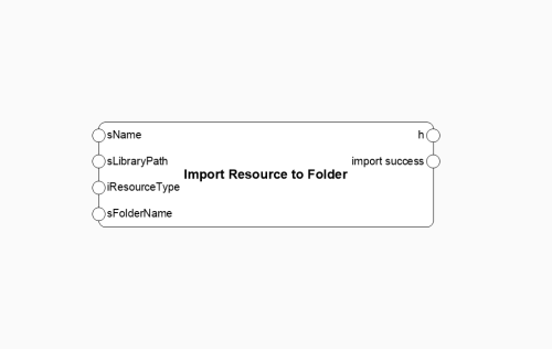
This node imports a resource based on the type into the active document and returns this object. With the input FolderName a folder can be defined where the resource will be placed. If this input is left empty, the resource will be placed at the top level of the resource manager. General: If the resource to be imported is already present in the document but modified, the usual dialog with change/overwrite, etc., will appear. It is not necessary to have the reference as a favorite or anything like that. The absolute path is specified. It is not possible to work with %userprofile% or %AppData%. Here is the documentation for the resource typs: LINK some of the common resource type numbers: Symbol: 16 Worksheet: 18 Record Format: 47 Hatch: 68 Line Type: 93 Texture: 97 ATTENTION!!! As is usual in Vectorworks, there must be no duplicate names. The node does not provide feedback if the folder name already exists. The folder will simply not be created if the name already exists. This does not have to be another folder. If there is a class/symbol or something similar with the same name, the folder will not be created. -
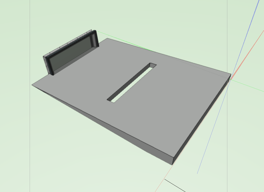
Hey everyone, I'm attempting to install a Velux roof light on a roof. It's nearly there, but the roof lights are appearing sideways. Does anyone know how to properly position the roof light? I'm sure this is a basic question, but I can't seem to find the option. Thanks, Jerome P.S. I have included the original SketchUp file from Bim Objects and an image of my specific problem. Any assistance is greatly appreciated. CFU+ISU1093-Curved-Glass-All-Sizes-V2019.skp

-
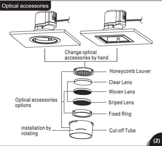
 Vectorworks should allow symbol insert in slabs. Like A walll , Slab is AEC componet and which should allow symol insert in either. We using Slab tools as ceiling / floor and slab in vectorworks. There are many Facilities and Fixtures in ceiling and floor. like: HAVC Lighting Fixtures Audio Power Socket Ethernet cable they all needed installation space.which is 3D hole componet in slab. same like wall. I'll illustrate an example. Here is a lighting speic. install a lighting require ceiling thickness to contain it's component ,which depends different lighting model. such as optical acc , It's not floating on ceiling , but in it . under Vectorworks 2024 version , if i wanna to represent accurate information , i need to build 2 Layer model . one is model itselt ,other is model which slab subtract to . while i wanna to move one lighting . i need to redo thi process. which workflow is the funtion" insert in walls" .
-
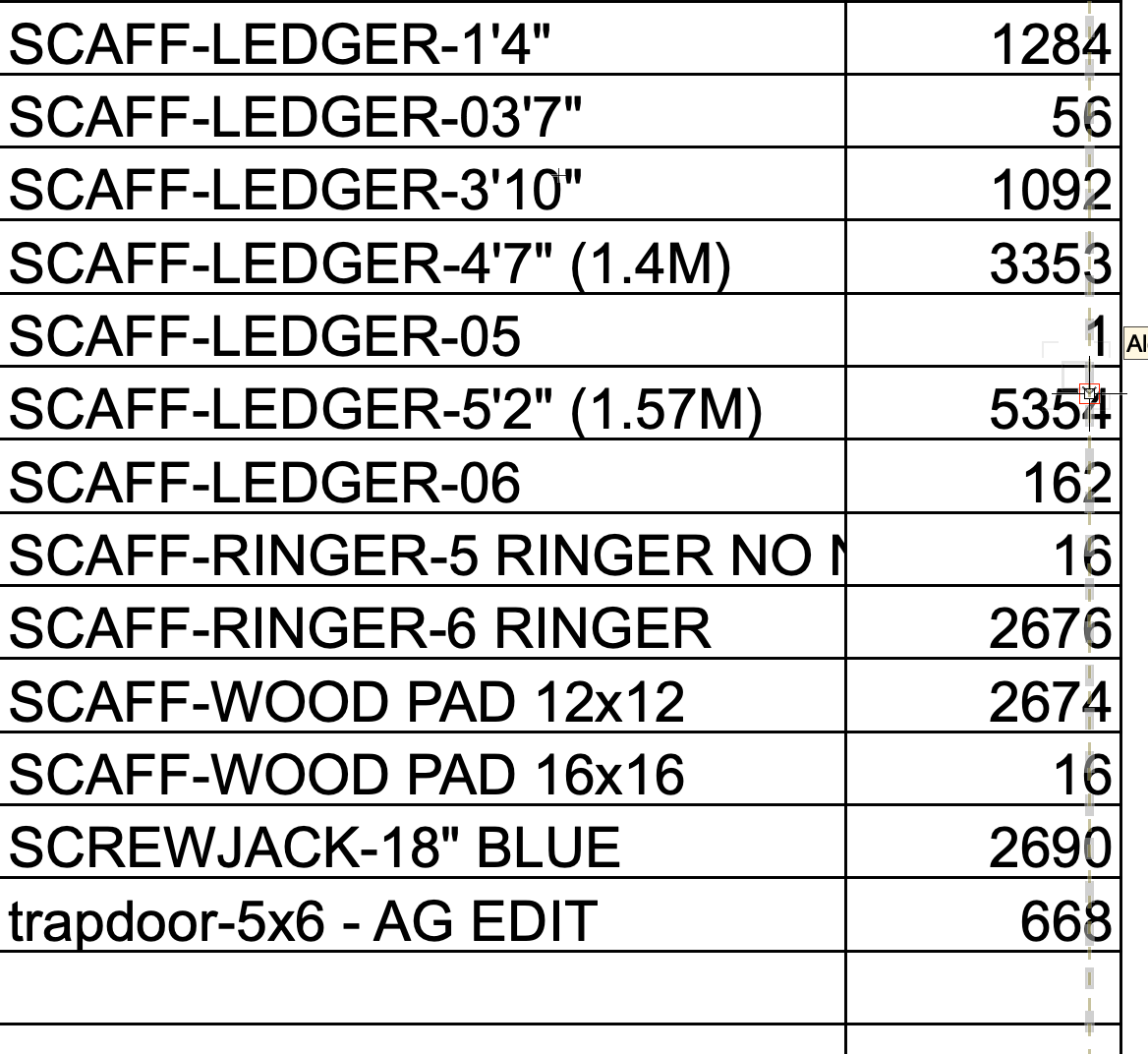
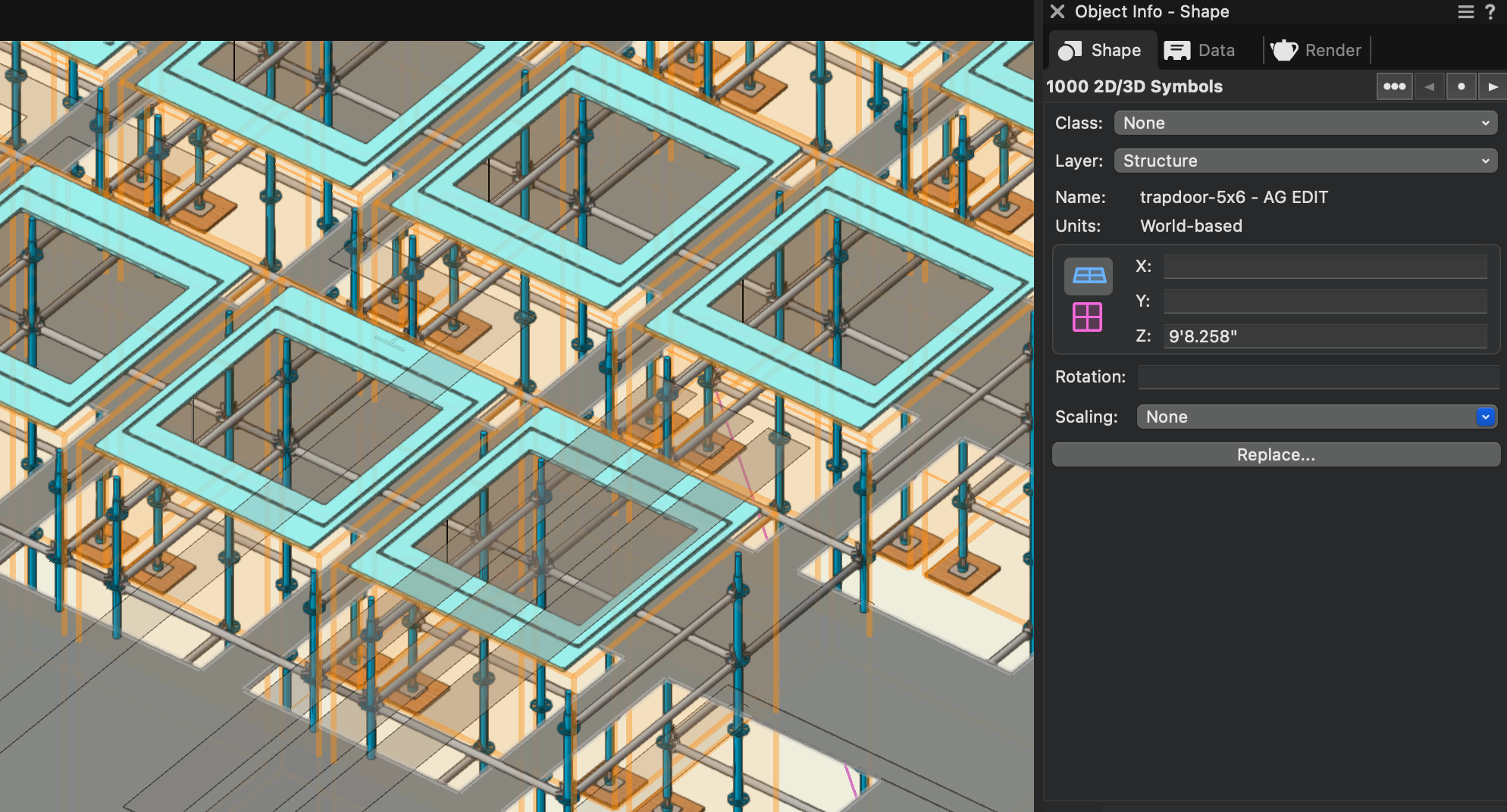
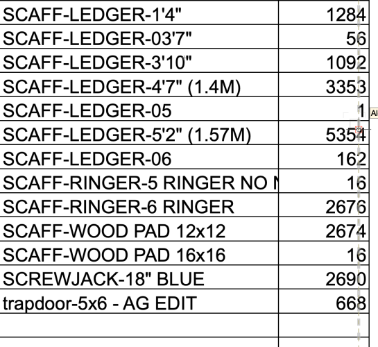
I'm drawing something that has 1000 of the same symbol, and inside that symbol are a number of scaffolding symbols and other symbols that I need to count. When I run a simple reports looking for Symbol Name and (Summarize by name) Count... It says 668. The nested symbols also show up as "X*668" instead of the proper number. When I use the Select Similar tool, it says 1000 as it should... anybody know what's going on? Is there a limit to how many instances of something Vectorworks will count? I'm concerned that if the count is off with the one thing I know how many there are... is the count for everything else in the drawing off too? Kind of defeats the purpose of the Report function if I have to go through and manually count out each and every piece of gear that the designer drew up.

-
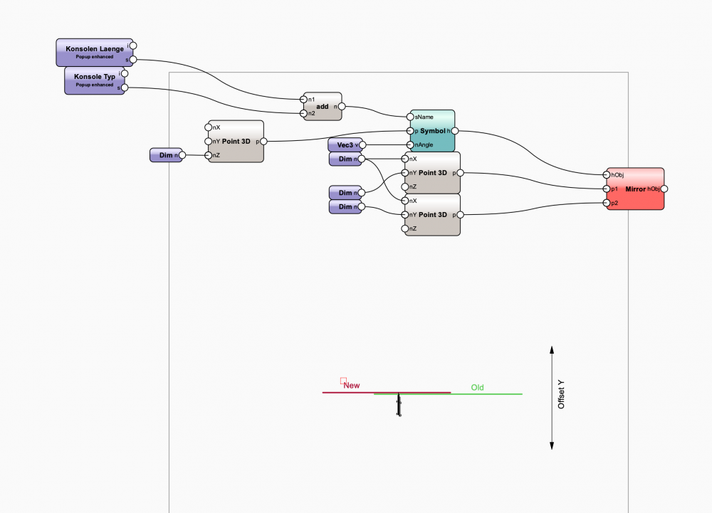
Hi, everyone I have two problems with inserting and mirroring symbols with a marionette. When inserting I don't get a Z position. When mirroring, the symbol is shifted in the Y-axis. Is the knot correct? Who can help? thank you Problem.vwx
-

1 of 2 types of Text in Symbol changes scale when file name changes.
SNOJNKY posted a question in Troubleshooting
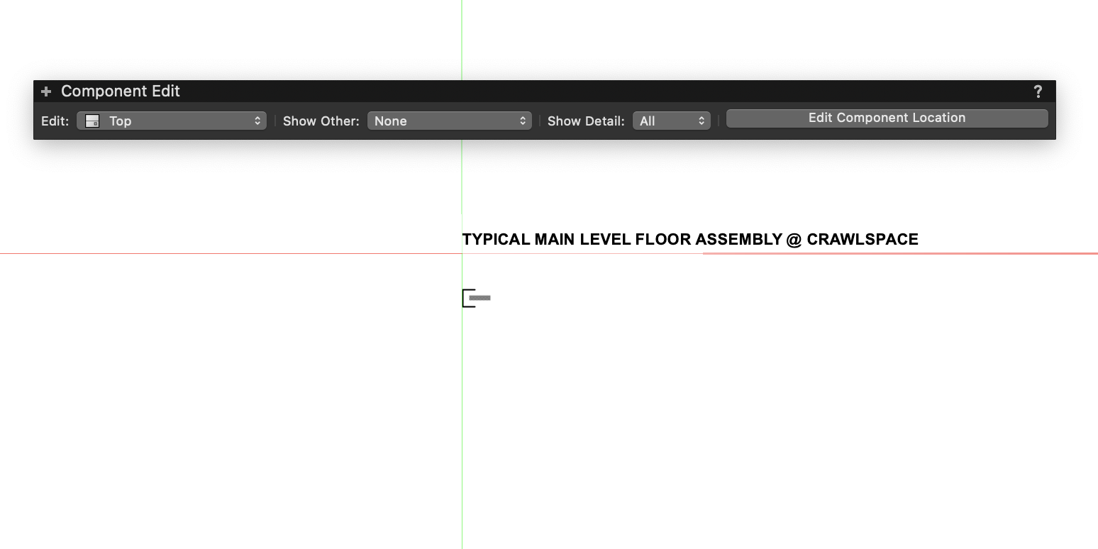
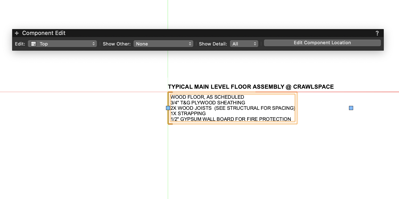
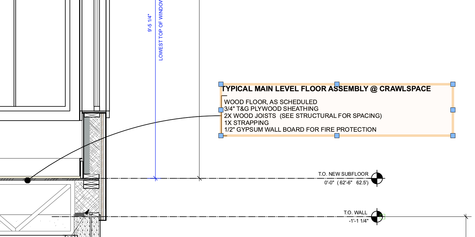
We've used text as symbols for years to annotate our wall sections. Within the last 18-24 months, there are many files where the wall sections are updated and the text in the callout is microscopic. To fix it, we have to double click to edit the symbol, go into the symbol and double click the text, exit the text, exit the symbol, and it is the correct scale. We've modified nothing. There are two pieces of text in each symbol -- the dumb text that indicates "typical wall assembly" then the callout text explaining the parts 'n' pieces of the assembly. Only the callout text is screwed up. This seems to be getting reset to microscopic scale whenever another user opens the file or we change the name of the file to the appropriate date. Also, why do I need to keep confirming that I'm not a robot as I type this message? 4 times, now. Images show the text scale issue. When "editing" the symbol, no changes are done -- just double clicking the callout to edit it and then escaping. Problem fixed. . . .painfully. We waste a ton of time updating every single text callout on every sheet of wall sections before sending pdf's. Help, please! -Carol (Still not a robot)


-
I used many symbols in my project. Now I want to find symbols with the same name and replace them with a different symbol. Which node can I use to get the name of the inserted symbol? Thanks for your help!
-
Hi forum, Is there a way to make polygon based - image prop for plant objects? I know there is a way to generate from image. I am looking for polygon based approach so I can have more control of line and fill color. Something like what Revit is having now. Thanks!
-
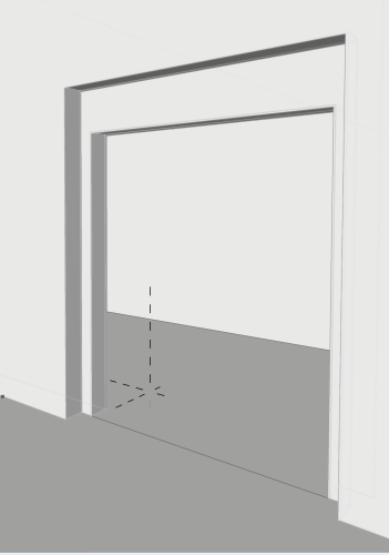
 Hi All, 2023 SP7 I made an extrude along path object (the lining and architraves of a doorway). Then, adding a 3D wall hole object, I created a symbol for insertion into a wall. ( I just needed a rough model of the existing doorway within an interior view which is why I didn't model a door in all detail with architraves). Despite all settings correct it was not possible to select the wall whilst making active the symbol....but when I deleted the EAP object (and added a simple extrude (a door threshold) to preserve the symbol) it inserted as normal. Has anyone else experienced this? Mark
 -
Hello, When I make an object a 2D symbol, the hatch I have it filled with is not visible unless I am editing the symbol. When I click out of the edit mode, the hatch reads as a white fill. What is happening here? It just started doing it. I have VW 2018. Thanks, Brittany
-
So I want to create a symbol that will vary in length and breadth according to inputs within the OIP. How do I do this? I know Marionet is a path but do I have to generate all of the geometry in Marionet for this to work? Built In Shower.vwx Thanks, Rudy Beuc
- 1 reply
-
- 1
-

-
- symbol
- symbol parameters
- (and 1 more)
-
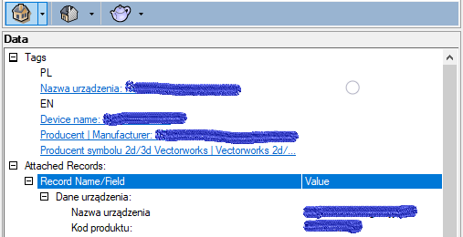
Hi, I'm wondering if it's possible to have one row data tag of 2d/3d Symbol in Resource Manager that half of it is not a hyperlink an the other is a hyperlink Like that Data Tags Not hyperlink: Hyperlink For now, I have to please Hyper links in another row to have this effect like PL, EN below If I have Hyper link after regular tekst in one row, the whole row becomes to be a hyperlink Any ideas, any clues?
-
 VW>AutoCAD question: --I want to export a VW drawing such that when I open it in CAD the following is true: all the parts/components/lines/groups/etc of a lighting instrument are on layer '0'. The actual symbol instance in the drawing is on layer 'Lighting-units'. --In VW, I've edited the symbol so all parts of the light are class '0'. When I insert a bunch of examples of that symbol in the drawing on class 'Lighting-units', things behave as expected: if I turn off either class, all the symbols disappear. --When I export to CAD, and try the same thing, freezing the '0' layer doesn't make the symbols disappear, but freezing 'Lighting-units' does make them disappear (as expected.) --In CAD, groups DO behave as expected here, i.e: the layer '0' still turns things invisible when frozen (the inner parts of the group are '0') as does 'Lighting-units' layer (the group as a whole is in this layer). Running VW2021 and AutoCAD 2023 all on PC. Here are my export settings if that's useful:
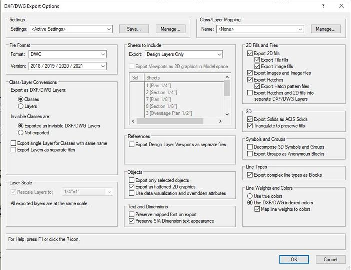
-
Long time VW user / script writer, and very novice Twinmotion user. Curious question that I hope isn’t to much of a bother. I’m curious if I have the ability to write a script/program in Twinmotion to substitute imported Vectorworks symbols with Twinmotion symbols from its internal library or user library. My current VW symbol library doesn’t have any materials attached to its 3D components so using the functionality to substitute materials during the import process within Twinmotion isn’t very helpful. I’m hoping I can write a simple script to substitute symbols but don’t know if I have that kind of access or functionality within Twinmotion to do that. Hoping someone might be able to offer some clarification to help guide my search in working Twinmotion into my workflow. Dave
-

2D/3D Symbols - Request for OIP Improvements
blanger posted a question in Wishlist - Feature and Content Requests
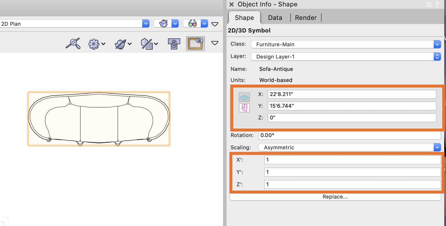
When selecting a 2D/3D Symbol I am requesting two improvements. • Ability to see the XYZ dimensions of the symbol in addition to the placement. • Ability to asymmetrically scale the symbol to a specific size rather than only proportionally as available now. In many cases, especially with furniture and appliances it would be helpful to see the current size and dial in a specific dimension. This would be really helpful for changing existing symbols to a targeted size, such as changing an existing refrigerator from the resource library to the specs from a manufacturer. Thanks!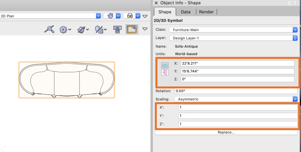
-
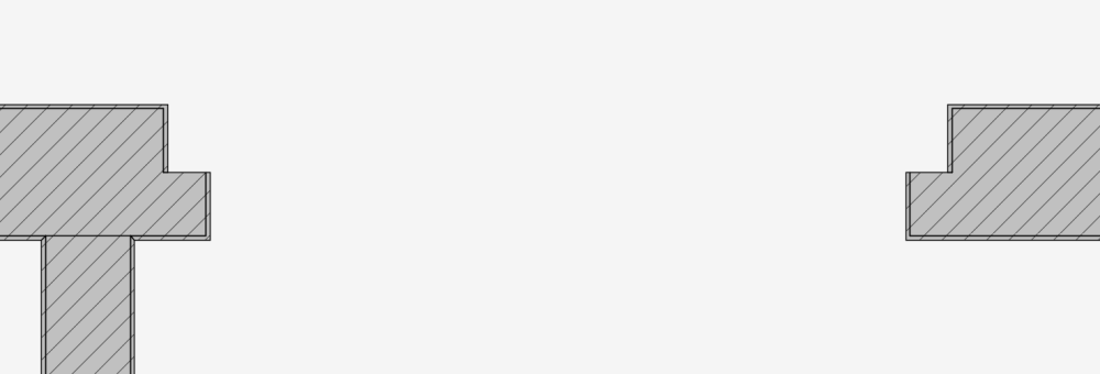
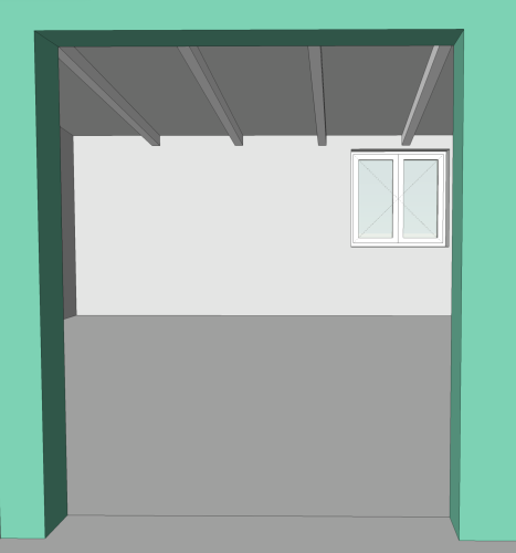
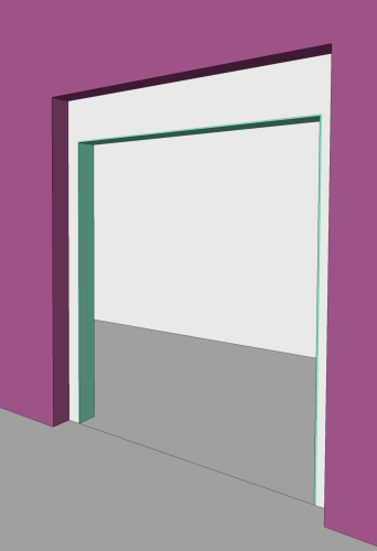
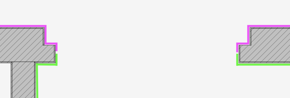
Hi, I am looking to find way to set up correct wall closure for custom opening. It is wall opening with stepped edges and am using symbol to cut it out. At the moment finish components of wall style stop where edge is stepped and will not wrap around to the desired place...tried different wall hole and wall closure components for symbol but no success so far... Here is case: view from one side (purple - finish component, gray - core, green - finish component) view from other side This is current state: and this is objective: Is it achievable using one wall style combined with custom symbol with wall hole and wall closure component? Would like to hear your suggestions. Thanks.

-
Version 1.0.1
267 downloads
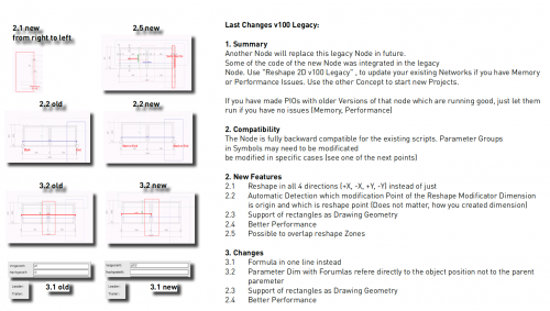
https://youtu.be/vuCvK4OwN80 German Movie https://youtu.be/Nm0te1zmpVY English Movie Structure of the Input: 1. Group with Geometry group (send to back) and Reshape Zone definition (send to front). Best practice is to use a blue smbol without screen plane objects 2. Reshape Zone group has further groups. Every reshape zones (polygons) is grouped with a dimension object. The dimension is the link to the script. The parameter name is a prefix of the dimension text 3. Use one of the existing examples to understand the system Limitations: 1. Supportes not 3D, Chain Dimension, path objects, rectangles. Container objects are not reshaped but moved (like the reshape tool) 2. user origin has to be set to vectorworks origin 3. not mix of screen-plane and layer plane. Use all layer-plane 4. ...- 6 comments
-
- 5
-
-
- parametric
- symbol
- (and 1 more)
-
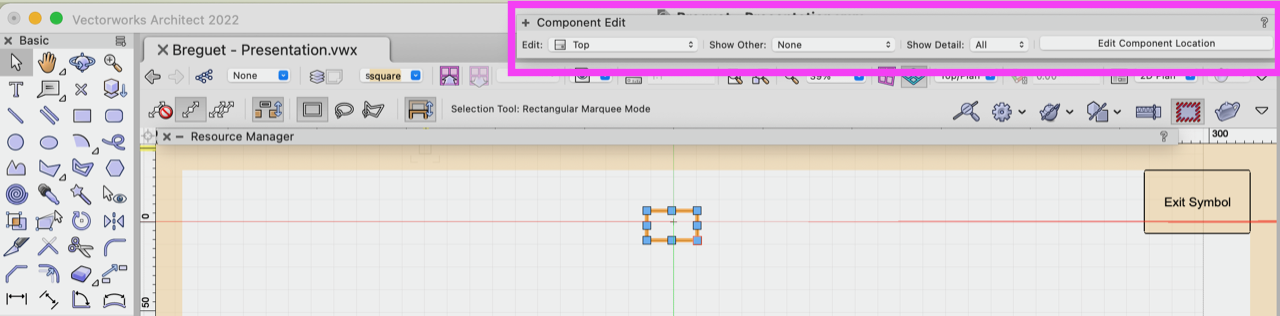
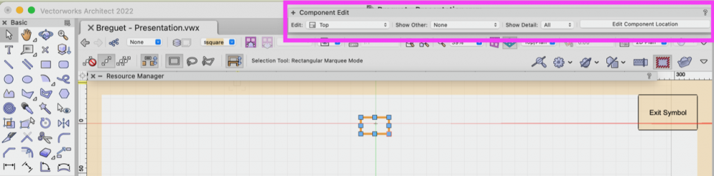
 Inside the Symbol Edit --> COMPONENT EDIT --> Save Palette Position currently not Possible. When working inside a symbol, the COMPONENT EDIT window pops up. It keeps sitting in the way of my drawing, which is rather inconvenient. Therefore I would like to save its position in a different location of my VW file. But when saving the Palette Positions, even when I am inside the symbol editing mode, it won't save the Component Edit position. Talking to my tech team, they say its currently not possible. Can we PLEASE consider an customisable location in the near future ?
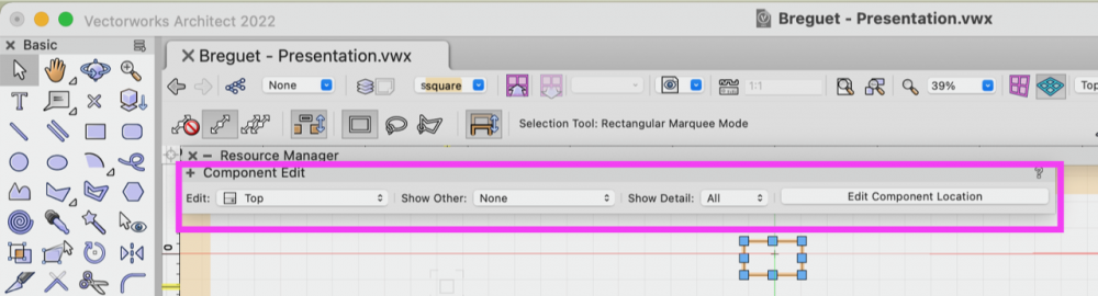
-

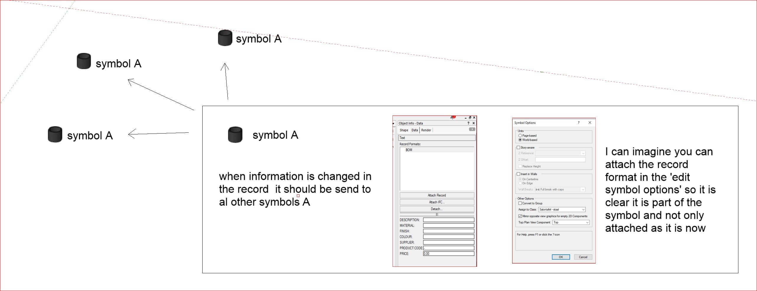
Records that work as a symbol
Bas Vellekoop posted a question in Wishlist - Feature and Content Requests
It would be great if we got the option to attach a record to a symbol with the possibilty to distribute the edited information in record to all other symbols with the same name. At the moment the only way to change the information in the record and distribute it to all the symbols is through a worksheet. This is not ideal, because 90% of the time you don't have the worksheet open or ready when you are editing info in the data tab of the OIP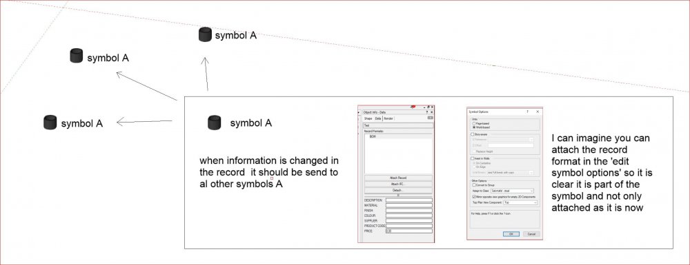
-
I'm trying to write a script that will allow me to generate an array of LED tiles with custom symbols. I'm looking through the reference documentation, I can not seem to find a way to prompt the user to select a symbol. Much like when you click "replace" you get the small selection window that asks you to select the symbol. Is there a function that will return the chosen symbol into a custom variable?
-
I am building a scenic element with repeated components which I am making using extrudes, add solids, and subtract solids. I am then creating symbol with each object, leaving instance in place, and using symbol insertion to place duplicates. The unusual result I'm getting is that the OIP is calling those objects "extrude," "solid addition," or "solid subtraction," and not "symbol." Also, the name of each symbol is not appearing in the OIP. Also, the symbols, inserted using Insert Symbol tool, do not update, when the symbol is changed using Edit 3D from the Resource Browser. Also, symbols I created in an older document imported to the new one, behave normally: display "Symbol" at the top of OIP, display symbol name, and respond to edits from the resource browser. I'm not sure what happened that I can't make working symbols anymore. Any ideas? Symbol Glitch.vwx
-
I can't modify door size in Object Info. How can I get this work? Thanks.
-
Hi all, I'm exporting a Cinema 4D file from VW containing a sport arena. I made a symbol of the sport floor, with all the lines for off side and so on. When I import this as a 3d-file into Twinmotion the symbol doesn't appear. Any clue why this is? Thanks!