Search the Community
Showing results for tags 'slab'.
-
Vectorworks should allow symbol insert in slabs. Like A walll , Slab is AEC componet and which should allow symol insert in either. We using Slab tools as ceiling / floor and slab in vectorworks. There are many Facilities and Fixtures in ceiling and floor. like: HAVC Lighting Fixtures Audio Power Socket Ethernet cable they all needed installation space.which is 3D hole componet in slab. same like wall. I'll illustrate an example. Here is a lighting speic. install a lighting require ceiling thickness to contain it's component ,which depends different lighting model. such as optical acc , It's not floating on ceiling , but in it . under Vectorworks 2024 version , if i wanna to represent accurate information , i need to build 2 Layer model . one is model itselt ,other is model which slab subtract to . while i wanna to move one lighting . i need to redo thi process. which workflow is the funtion" insert in walls" .
-
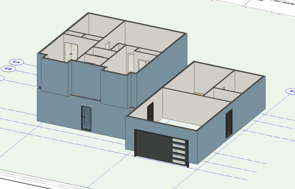
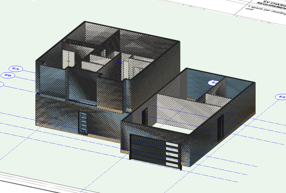
Hey Guys, I am having a severe issue with a particular project that I am working on that is going to have to lead me to redo a clean file from scratch, but I thought I would ask for help anyway. This model breaks when you add a slab to it. I have tried everything to isolate the issue but I cannot figure it out. Here is an image of it before adding a slab: And After: Nothing fixes it unless you delete the slab, but even then sometimes it just stays broken. When you copy it into a blank file it corrects itself. You also cannot see the Slab in 3D view, only in 2D. Then the whole file breaks down and many errors start occurring. Please let me know if you can fix this or if the problem is replicated on your computer. MESSED UP HOUSE.vwx MESSED UP HOUSE.vwx
-
One thing I don't like about auto-bounded Slab/Wall connections is that the connections fail so often. But the reason I don't actually use automated Slab/Wall connections is that when the Slab/Wall connection fails the slabs default to their original shape. I would be more inclined to use auto-bounded Slab/Wall connections if they retained their current shape when failing. The vast majority of time that I see the Slab/Wall connection fail I haven't actually moved the walls. If the Slabs had stayed in the shape they were in everything would still look fine. The downside of having the Slabs retain their shape after a connection has failed is that it wouldn't be obvious that the connection has failed. But there's got to be a better way of letting the user know this than simply trashing the whole connection.
-
Tool to connect wall, slab and roof components
DaleW posted a question in Wishlist - Feature and Content Requests
I've been trying to connect the below roof and wall so the components join: It would be great if there was a join tool that could connect components between walls, slabs & roofs. this would be perfect for construction documentation. Without this tool I have to trace over each junction such as the above in annotations which is annoying. -
I've found that any Hardscape object created in Vectorworks Landmark 2021, which is set to 3D Type: Slab and has the Slab Components Datum set to Top of component (i.e. slab extruded downwards from the Hardscape object's elevation value), has zero thickness when the .vwx file is opened in Vectorworks Landmark 2022, and the Main Area Components and Border Components buttons of that hardscape object (which you'd use to correct/adjust the thickness) don't work in the Object Info Palette or the Hardscape Settings. When the buttons are clicked the usual settings box doesn't appear. I suspect this might have something to do with the fact that in VW 2021 the Top of component option causes the 3D slab thickness to be displayed in the OIP as a negative value, whereas in VW 2022 it is displayed as a positive value (despite still being a downward/negative extrusion). Has anyone else encountered this and found a solution? I've got some big files with large numbers of hardscapes set up this way, many of them inside symbols, and it would be excellent if an update to VW 2022 would allow them to be correctly translated to the new hardscape format, retaining their thickness and the ability to edit them.
-

Add Profile (to almost anything) Tool
mgries posted a question in Wishlist - Feature and Content Requests
A great addition to VW would be a universal profile tool that could be applied to multiple plug-ins and modeling objects. I'm imagine a new category in the resource browser that stores simple polygonal profile shapes (as profile symbols). Many plug-ins could then be improved to include an "add profile" function or "add edge profile", depending on the context. Some likely candidates for this feature... roof (at eave or rake) - at edge framing member - at end condition (i.e.- decorative rafter tails!) extrusions (already uses profile but now profile would be a resource) slab (at edge or boundary) wall recesses and projections window/door sill and trim etc... Matt -
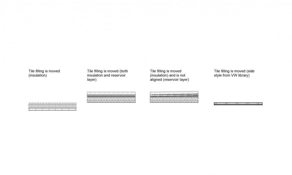
Hello, I have some problems with Tile fills in my slabs. I tried to create own Tile fillings for my slabs, but they all fail in sections. As I noticed even built-in Tile fills do not work properly - they are moved, not aligned etc. I tried many combinations of settings, but still either I am missing something or it just does not work. Picture and file in attachment. Slab test.vwx
-
Hello, From time to time I am experiencing some nasty issue with slabs that have adjusted edges ('Edge Offset') . Order of edge numbers get somehow renumbered and numbers becomes shifted so in effect causing edges offset disorder. I've had just this happened at once with all slabs present in a file with adjusted edges. Sometimes happens to only one particular slab. No idea what trigger this kind of behaviour... anybody experiencing this issue...and have someone find reason what is the cause and what to whatch out. Updating slab style...? File was originally created in vw 2020 and now migrated to 2021. I definitely see this issue across other files too. Or is this a known bug? Thanks for your help.
-
Slab component visibile in top/plan even if class is not visible
StefanoT posted a question in Troubleshooting
Hello, In Top/Plan view - both in DL and in SLVP - slab components are visibile even when component class is set to invisible. In 3d views everything seems to work as expected. Is this working as designed? I am running VW2021 SP2 on Mac OS Big Sur. Attached both video & vwx file. Thanks in advance for any help! VW2021 - slab component.vwx Screen Recording 2020-12-17 at 22.16.33.mov- 3 replies
-
- slab
- slab components
-
(and 1 more)
Tagged with:
-
Hi, So, a couple of thoughts: 1. If I combine all walls, slabs, pillars and stuff to one piece of combined solid, will this make a lighter file? 2. If so, how do I do this? I want to make one piece of solid made out of all the walls and slabs I've created. 3. Is this even a good idea? I'm making an arena, so there's gonna be a lot of stuff in the final file, so it needs to be lightweight and easy to understand. Thanks!
-
Why are roofs calculated from the bottom?
NickMac posted a question in Wishlist - Feature and Content Requests
So I have been using Roof objects as roofs and as ramps/slopes. I believe this is fairly common practice. Why on earth does vectorworks calculate everything from the bottom? We use Top of Ridge RL's, Roof Edge and Gutter RL's. Top of slope RL's and Bottom of slope RL's. Never in all of my architectural experience have I wanted to set the bottom of a sloped object to a specific level. When designing, the important features are on top of a sloped object. Apparently from the VWX perspective it is intuitive to set the bottom of the slope to the Top RL minus the cosine of the slab thickness to set the Finished Level. ??? It would make more sense to set the top of roof RL's that correspond with the top of the slope/roof, and let the roof thickness move down rather than up. Same for the slab tool. Why would I set my slab to -250 from the finished floor level and then add thickness on top of that. If I change my floor construction it just means that I have to get all my slabs and move them up or down. Surely it would make more sense to set a slab to the finished floor level, then let the slab thickness move the bottom down in the Z axis. -
Hi, Super basic question I guess, but I can't seem to find the reason why this doesn't work. I'm trying to add a slab to my walls, but nothing shows up. Please refer to short clip I added. Warm regards and thanks all! Martin Slab question.mp4
-
Anyone got any ideas how to connect this wall & roof so the components follow through? Vectorwork's biggest downfall for me is its lacking ability to connect slab, roof and wall components to each other. It would be great if there was a join tool that worked between these items.
-
Working on building a worksheet where clients and users will see the composition of the slab styles that will be used in Hardscapes. I've managed to create in the attached just such a thing but have run into a little difficulty. When using a function to get the thickness of a component it is adding all of the components regardless of which slab they are a part. The attached file has our slabs and the worksheet with the cells in question. My vulnerability is Worksheets and I'm learning more every day but I really could use some help on this one. Your time and effort is greatly appreciated! Have a great weekend! Slab Styles.vwx
-
So I have a slab and I want to have different class textures or textures on it. What do I do to make that happen?
-
Hi all! I'm having an issue where not all geometry is being represented in a section viewport with the same line type and weight. I've attached a screenshot. I have four slabs represented in each of these viewports — two concrete slabs on different stories, a floated floor, and an interior ceiling. The lower concrete slab and the ceiling are representing with an open-end whereas the floated floor and the upper slab are "closed" and have a border around them. The two concrete slabs are the same slab style and in the same class but appear with different styles. I can't for the life of me figure out where this is modifiable from. Any help is appreciated!
-
- slab
- section vieport
-
(and 1 more)
Tagged with:
-
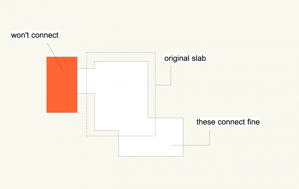
any one have this issue??: I have a slab with about 7 components; I draw a standard rectangle and create a slab , no problems, I then add another rectangle (overlapping) and select both and add surface, all works , original slab is extended. If however I try to add another area with the same add surface workflow, it will not join onto the slab, unless its a new edge of the original slab. note - it seems to work fine if the rectangle overlaps the original slab but will not extend an already extended piece... ie. the orange bit won't add onto the white slab bit slab.vwx
-
Hey Guys, I'm having issues with my section viewport where a line from the a slab object is showing through a wall. In the attached images, I've circled the three instances where a line appears where it should not. I have tried moving the slab far beyond the wall, but the line still displays. The line disappears when I delete the slab object and update the viewport. The strange thing is, when I pull the clip cube away from the building for an elevation, the lines disappear. Let me know what you guys think the issue is. Thanks, Raymond
-
Hi, "This is a repost from ealier. I didnt get any answers, so i thought to try again" I have this floor made of following layers, Sand, concrete and tiles. The two first layers is just flat and wall to wall. But the tile layer has to have a virtical edge. In my test file, did I use the slab tool with the three layers, and afterwards did I make a 3D object, added that to the slab and so on. My problem is, that the top layer (tile layer) dosent follow the wall anymore. So is there a way to make the little edge, and still keep the auto-bound to the the wall? I do also need to have a drain in the floor (like in the file) I have attached a file, with my example. Test.vwx
-
I have created a slab style that has the flooring, floor joist, ceiling battens and ceiling. It works great apart from the edge texture can't be set. As per the image below is it possible to create an additional component that can be classed the same as external walls and that sits in the same Z height as two of the other components.
-
Does anyone know how to get an area output for slabs in a 'slab data' worksheet?
- 3 replies
-
- worksheets
- slab
-
(and 3 more)
Tagged with:
-
I’m not sure how most people generate 3D object, but in our office we turn 2D polygons, rectangles etc. in hardscapes, then in the Object Info, under 'Draw 3D’ Go: 3D type > Slab. Then from there you can edit slab thickness, elevation etc. In VW 2016 you were able to set negative thicknesses to the slab. For instance: say you have a step at a height of -600 elevation then you set the step thickness at -150. You know the top of the step is at a height of -600 below 0 and then another -150 down to the next step, starting the next step at an elevation of -750. In 2017 it seems you can’t set a slab thickness of less than 0 anymore. Meaning, if I use the same example, if I have a step with an elevation of -600 (this you can do in 2017) and enter a thickness, I have to enter 150 to get the same effect however the elevation of the step will be -450 now. The next step after this one will then need to be -750 at 150 thickness to give it a height of -600. Doing this for all 3D Hardscape-Slab objects in a drawing becomes incredibly confusing and makes us question our accuracy at every change therefor slowing production down to a grind... Could we have this changed back to the way it was? Cheers, Dan
-
Slab modification and context objects
David Poiron posted a question in Wishlist - Feature and Content Requests
It seems that when you "enter" a slab object it does not show the context objects like when you enter other similar object types. Not sure if this is a bug or something not implemented or I am doing something wrong. I often have to modify the underlying geometry and snap to surrounding objects. -
I have a long narrow roof that I would like to create a centre valley with multiple drains and saddles in between each drain. I can link the first two drains together and create a saddle but when I try to link the second two it gives me an error about 160 degree angle (see attached). Is there a way to do this?
-
The more I build BIMish models in Vectorworks the more I find I'm having to recreate slab styles as roof styles and vis versa (sloping ceiling, ramps in slabs,...).Either of those as a wall style is also useful for generating details and the wall tool being the best for laying out lines of shell detail. The problem being I end up with two even three resources to then describe what is effectively intended to be the same system. It would be good if the three separate shell styles could cross-over between all the shell tools.


