

Search the Community
Showing results for tags 'render'.
-
Hi I am trying to render a scene using custom lighting symbols and have the color of the output react to the viewport class color set. I have created some custom fixtures and have a lens in one separate class and the light source in another. When i change the color of the viewport classes to be different than the classes of the main file, only the lens class actually changes color in the render, and not the light sources. The sources are the same color as the main class color, and not the viewport class color. I have the light source in the 3D model set as style solid fill and color to class style. The lens has a texture with color set to "object attribute". Is there a setting somewhere that needs to be changed in order for the viewport class to set the of the light source? Or is there another problem?
-
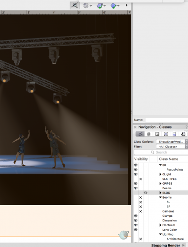
Hello; excitedly installed VW 2019, opened a current model small model (4 trusses, twenty four spotlight fixtures turned on, sixteen with fog) and hit render. After an hour and change; I decided to stop the render process and the two choices I am aware of have failed to stop the render. Hitting escape = no joy Hitting Cmd + . (period) = no joy either. Also, VW 2019 shows "Stopping Render" in the message area, yet does not stop… Thoughts? TiA
-
I've been trying to find the solution to this for a while, but I'm not sure if I'm googling the correct terms. I want to make the Borders of Hardscapes more real-world accurate. When I apply a texture to the Border Slab in the Object Info, it visually looks like the rest of the hardscape (i.e. a seamless texture repeated across the plane of the surface). This hasn't been an issue in the past, but we recently showed some renders to a client and they fell in love with how "unique" and "creative" the pattern of the border was, and we had to explain to them how this was just representational and not accurate to what we normally install for borders. I'm struggling to insert URL images to show what I mean so here are some hyperlinks instead: How the paver border looks in Plan View Render shown to Client An example of the look we're trying to achieve Is there a specific setting somewhere to make Renderworks textures align to curves and look how they're supposed to, or some workaround? I'm working in Vectorworks Landmark 2023 SP6 (Build 711238) (64-Bit) Thank you!
-
2023-07-25_20-35-53.mp4
-
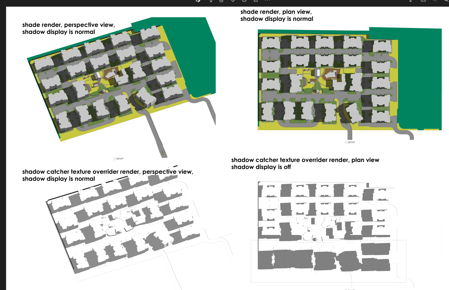
Hi, I am working on exporting a shadow drawing with Shadow Catcher Texture, and VW generates a strange shadow display glitch and I can't figure it out. The viewport will correctly render shadow in a perspective viewing angle, but when I switch to plan view it will go off - buildings on plan bottom will be covered by glitching shadows. Please see attached images. The working file is also attached, I am using Landmark 2023, please let me know if you have comments. Thank you. 1118363379_testfile.vwx

-
-

Automatic Camera Vertical Tilt Correction
martinfdc posted a question in Wishlist - Feature and Content Requests
Hi, It would be very useful that the Vectorworks camera would have a feature that allows one to make sure that all vertical lines are vertical. Similar to what a perspective correction lens does in a real camera. With this new tool we could make sure that all of our renders come out with completely vertical lines and a great perspective instead of one that is deformed. It would also make things faster as one would need to fiddle less with the camera in order to get vertical lines. I attach a photo that makes clear what I'm talking about. I took the images from V-Ray for Cinema 4D Manual: http://vrayc4d.com/live/vrayforc4d-manual/vray-physical-camera/vray-physical-camera-examples/ V-Ray has automatic vertical tilt correction. Hope this gets implemented!
- 5 replies
-
- 7
-

-
- camera
- renderworks
- (and 3 more)
-
Hi, I use VW but two of my colleagues will be modelling in Sketchup. Are there any tips on workflow? Ie guidelines on how to best export and import? In the past I have found models I've imported in VW from SU to be very fragmented and need a lot of cleaning up. The person I'm working for will model in Sketchup and then ask me to import the model into VW to produce working drawings He'll also want to make changes to the model (in VW) and then also texture and light for rough renders. Then pass the model back into SU Is this possible? or better to just transfer it once from SU to VW. Any tips on how I can save hours remodelling / fixing up the model so it is editable in VW? much thanks, Helen
-
does anyone know if there's a way to turn off the default map type of 'surface UV' in VW 2022.SP.3. and use auto-align plane as default instead? The surface UV gets applied to any extrude etc and is a complete mess when in C4D (UV wise). Walls etc are auto-align map type and UV's are correct in C4D.
-
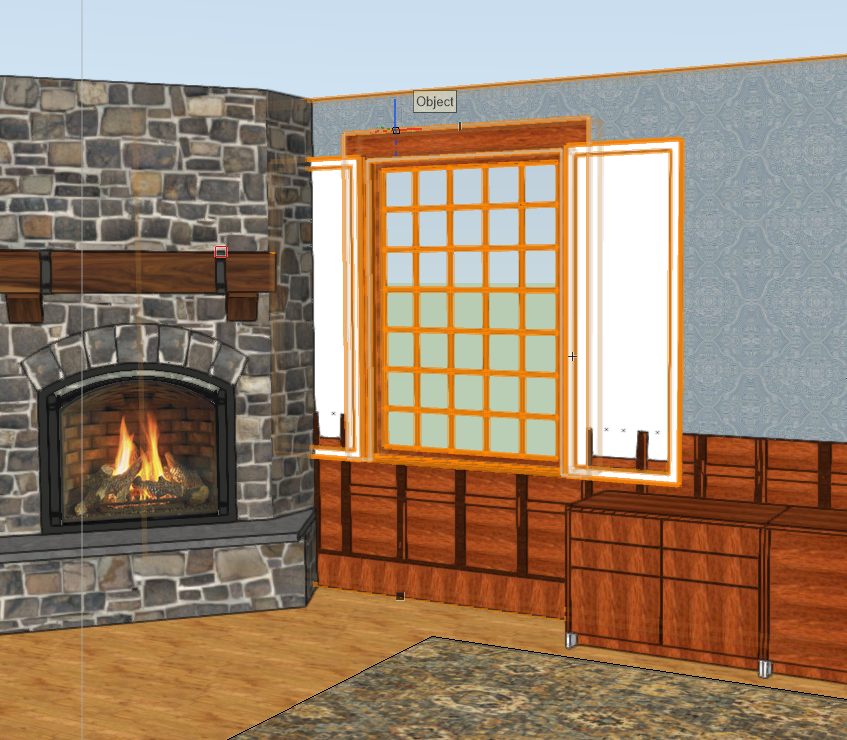
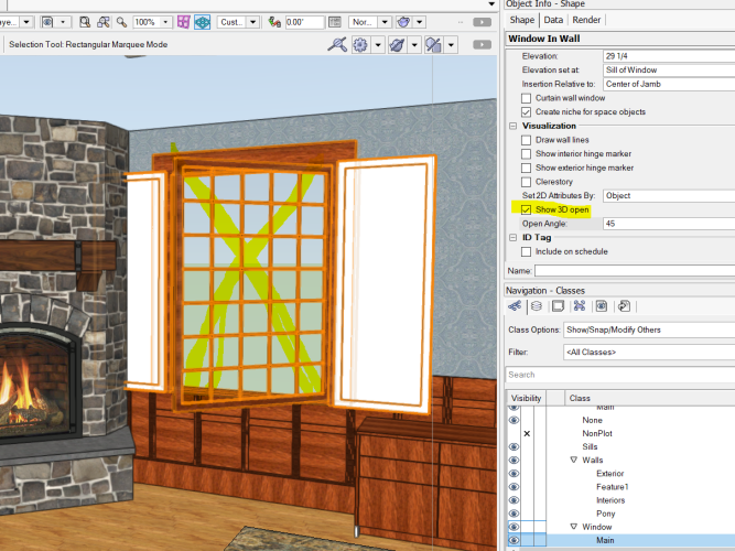
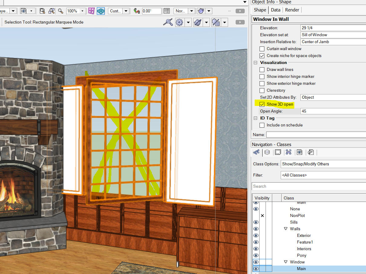
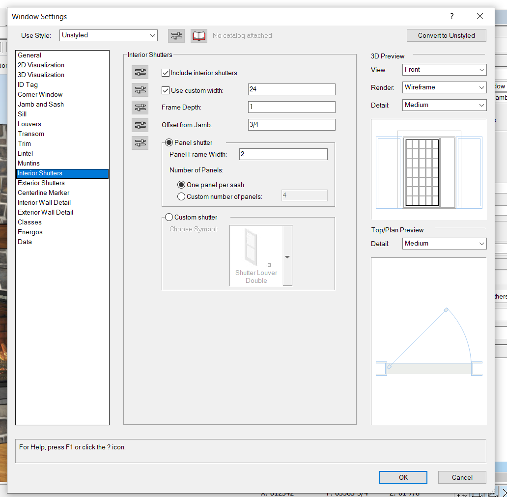
Does anyone know how to open just the window *shutters* in 3D? If I set the window to open, the inside glass opens which is not what I want. Without opening the shutters, millwork and other things show through them. I would also LOVE to be able to easily make these shutters bifold; currently that's not an option. You can change # of panels but that just splits things horizontally, not vertically. I don't see any option for this in Window Settings either: Hoping some VW folks see this 🙂 Thanks! Marci

-
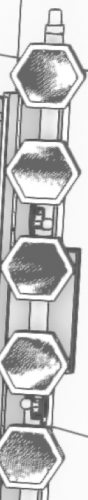
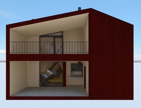
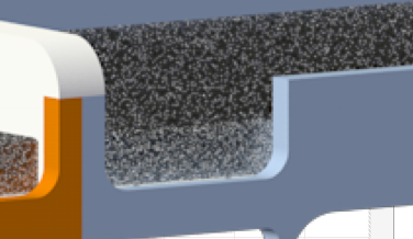
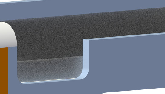
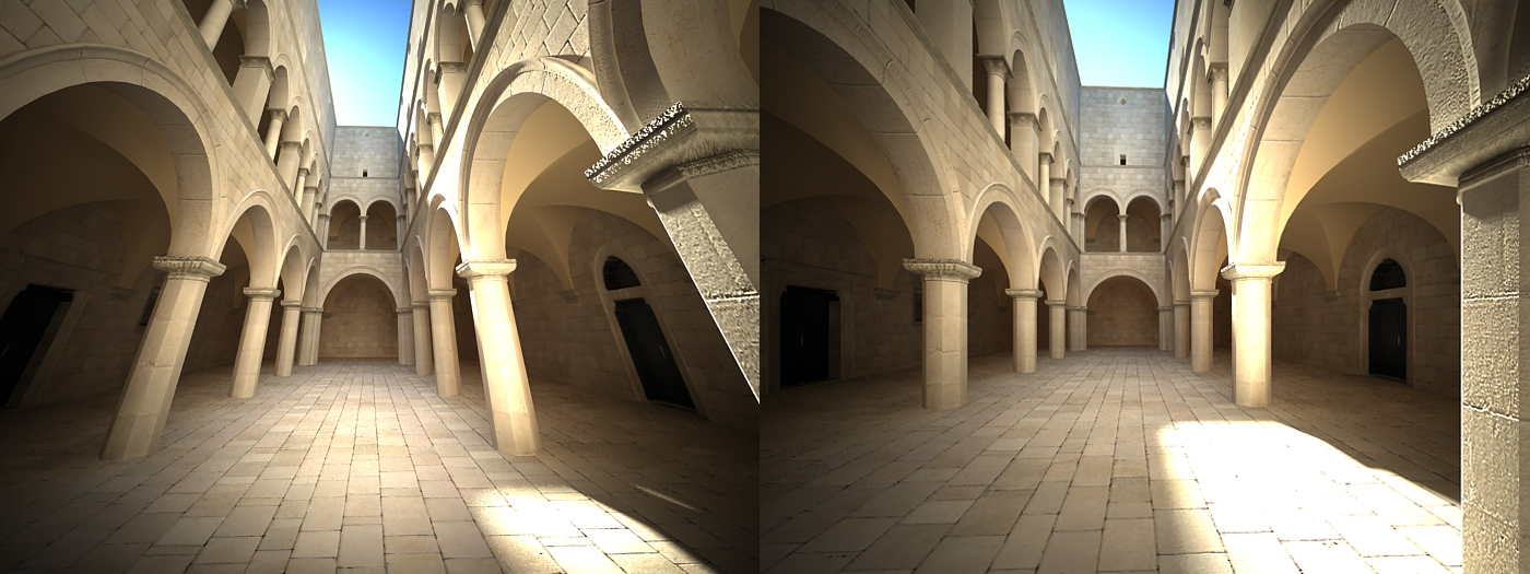
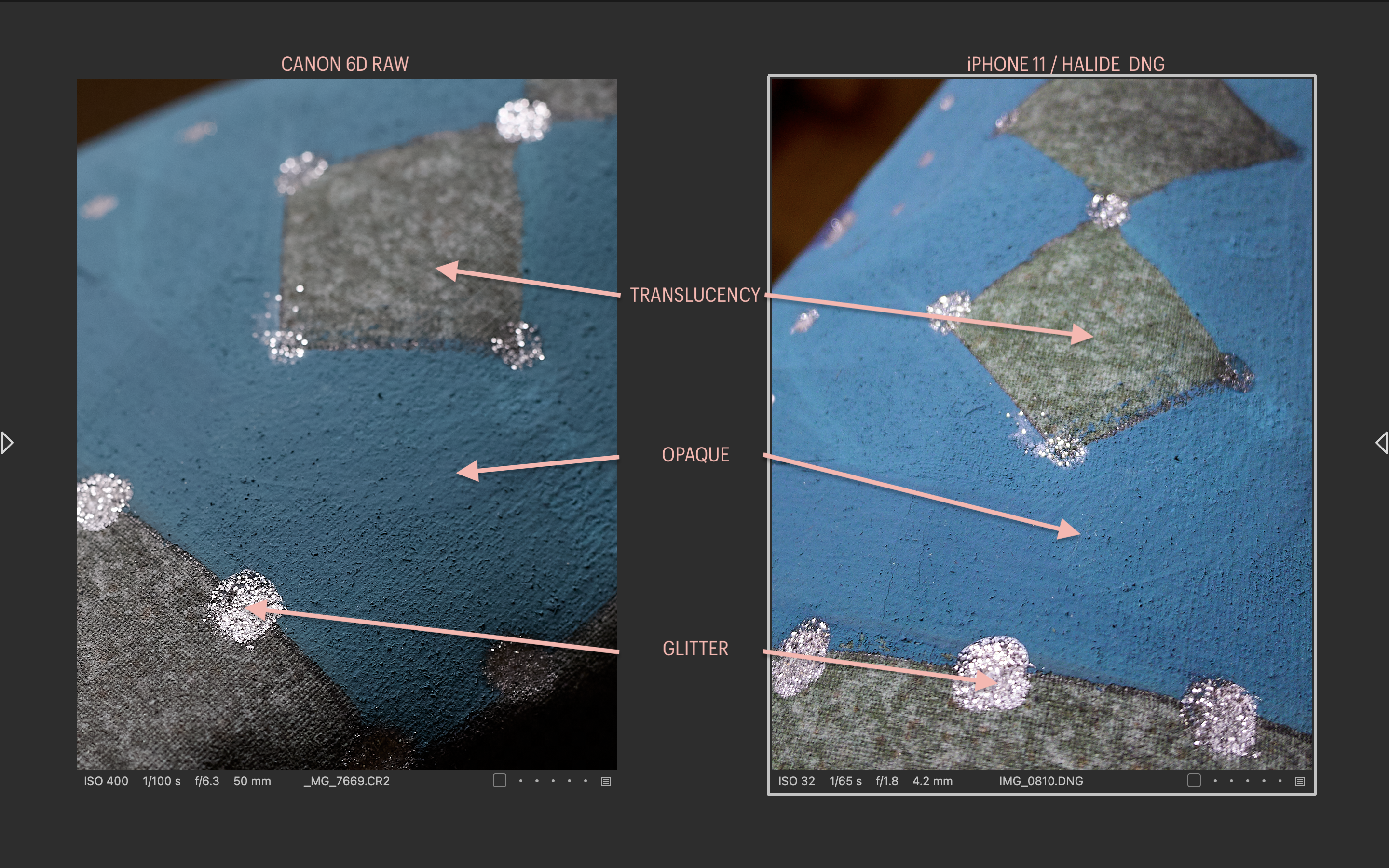
Alrighty then; I have a scenic drop to light, quite traditionally executed, to my general delight. Got all wound up in the idea of previz-ing a few ideas in Renderworks (def not Vision) for the client. The few times I have executed this idea in the past, the drops have been either simpler in execution or I knew less then or both. This time the drop has the following attributes: opacity varied translucency specular highlights (glitter paint) My solve so far has been: image prop for the overall drop, with translucency determined by luminosity in PS translucent cyc behind that this covers all but the specular bit. Help? The attached image shows a close-up of the paint sample. The drop overall is a sub tropical cityscape. [The side-by-side is just because I got suddenly interested in who's interpretation compared to IRL worked best. The Canon (2012) for color accuracy's sake kicked the iPhone 11/Halide Raw's ass all over the kitchen floor to my eye, as it was shot in daylight and directly compacted to the paint sample. Punchy as the iPhone/Halide version is, it's much livelier (& plain wrong) than the reality.]

-
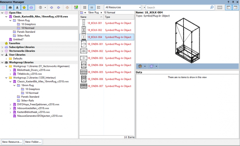
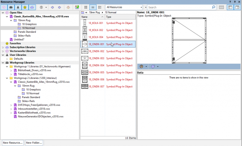
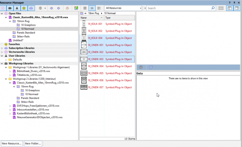
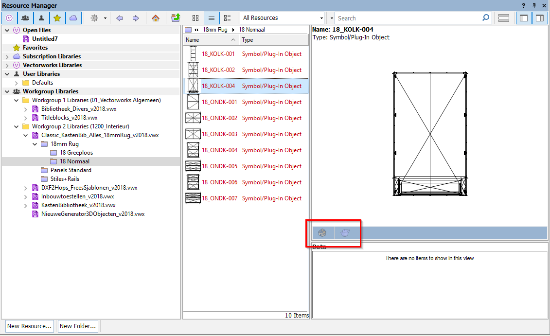
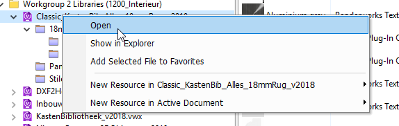
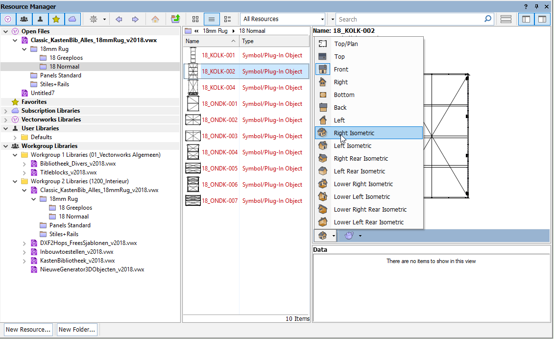
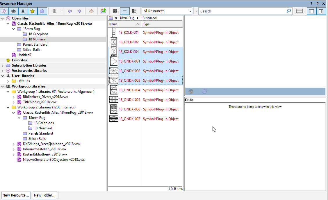
 I have 2 requests for the render and view mode in the preview pane of the resource browser: Please allow us to change the view and render mode when the file in the library isn't opened/activated. When not active, these 2 functions are grayed out: These buttons are enabled when the file is opened and i's the active file: Is it possible to enable them when the file isn't opened? Let the system remember the chosen render and view mode when the selection changes: The third symbol is selected and I've changed the view mode to right iso: When I select another symbol, the view mode is the default again: Wouldn't it be better if it remembered the last view & render mode? This would mean that you have one preference for all you symbols. Or is the vision of VW that every symbol has his own view preference? If this is the case, could you allow us to change the view & render mode of multiple symbols at once? Not possible atm, the symbols are grayed out again when we have multiple symbols selected: Thank you! Bert
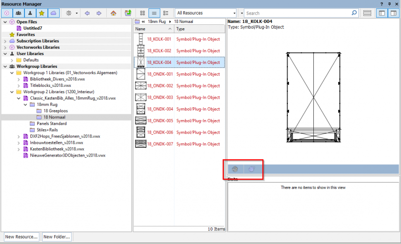


-
Vectorworks Community! I need some help with surface hatches. I have a brick texture on some of my buildings and have amended the surface hatch so that it appears lighter in 'Hidden Line' render settings (see attached image). The problem is when I create an elevation viewport the surface hatch appears really dark in the 'hidden line' render settings (see attached image). What settings do I need to change to correct this? TIA.
-
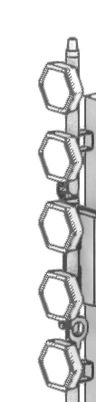
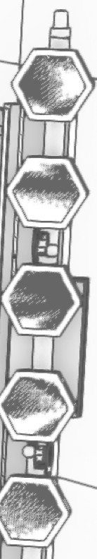
Please see two screenshots attached below... The first image is a screenshot taken from a design layer in OpenGL, when orbiting the lenses remain clean and exactly how I want them to render. The second is taken from a sheet layer of a viewport, rendered in OpenGL only this time I get random artifacts appearing on the lenses of this particular fixture. My first thought was that there may be some overlapping geometry (although this doesn't explain why it renders correctly when in the design layer) regardless, I tweaked the position of this polygon but no success. I also played around with crease angle, removing texture, setting solid colour, various lighting settings, turning off ambient occlusion and DPI settings of the sheet. Any suggestions on a fix would be greatly appreciated. Many thanks Dan

-
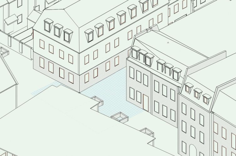
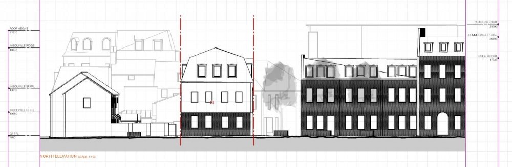
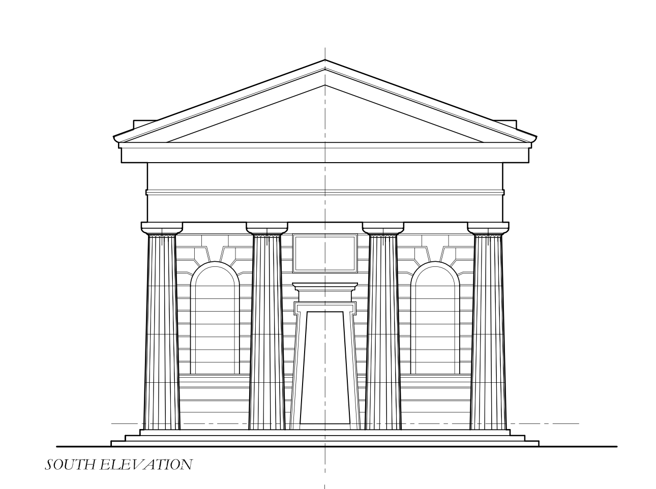
 Hi, I am wanting to create a detailed building showing the unique brickwork on the facade of the building. How would I do this in the most efficient way? Below is a screenshot of the elevation of the facade. Would be great if anyone can help. Thanks
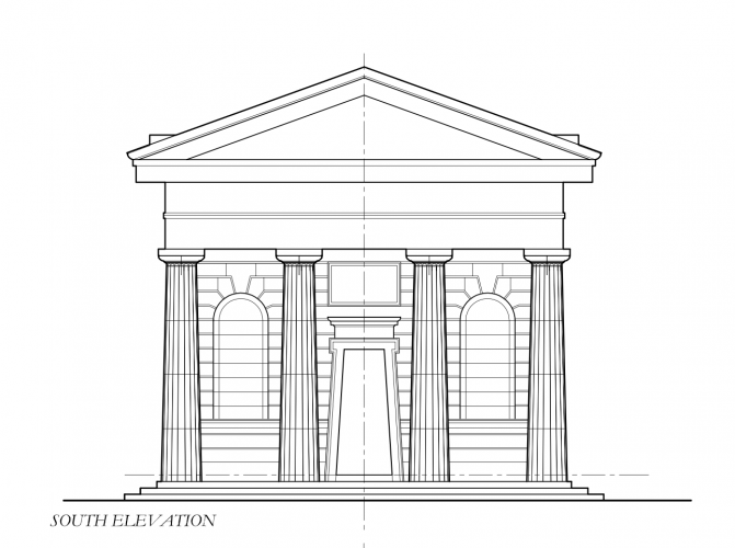
-
After the upgrade to 2021, realistic Rendering doesn’t work at all for my current project. When the render is done it warps whatever is seen through the windows with the Glass texture and generates really really bad artifacts all over the render. I have to go back to Vectorworks 2020 until this is fixed.. Really dissatisfied with an upgrade that causes so much problems. Is this a common bug or is there a change in settings that can correct this? If it is a bug I don’t understand how you have missed such a big problem in quality control.
-
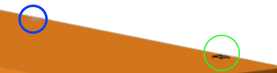
Hi everyone, I have notice that there is problem which I am constantly coming across with. Quite often, the renders I do result being different once I render them in a viewport window. For example: This is a render I did on a design layer and both shape and texture look fine. But then, when I render through viewport on to a sheet layer, I end up having a different image: The image looks blurred and the texture lose its original color. I tried to scale up the viewport scale to see if at a bigger scale the resolution would change: and the image did improve in terms of sharpness but still the texture's color would not match the one I have in the design layer. Another odd mistake I've bumped in to, is this: It did happens a few time now, that when I render a solid, on the final render image comes up a shape that is not supposed to be there. In the green circle there's this black form that does not appear in the design layer as solid. In this case the green circle should result just the same as the blue one. All these little inconsistencies, often showed up in the final renders and even If I go back to try to sort them out I will not find the solution. I am wondering if this could be due to hardware performance that are not matching the software requirements or maybe some render settings that need to be edited? Once again, thanks for your help. F.


-
I'm writing an script that will take each symbol(_i in list of symbols) from the resource folder makes an render and places it in an folder. for _i in _lSymbols: _Renderlayer=vs.Layer('Render') _hRenderlayer=vs.ActLayer() vs.Symbol(_i,0,0,0) vs.DoMenuTextByName('Standard Views',8) vs.DoMenuTextByName('Fit To Objects', 0) vs.SetLayerRenderMode(_hRenderlayer, 6, True, True) vs.DoMenuTextByName('Copy',0) vs.DeleteObjs() vs.DoMenuTextByName('Paste As Picture',0) _hImage=vs.LNewObj() _iRenderFolder=_RenderFolder+ '\\' +_i+'.png' vs.ExportImageFile(_hImage,_iRenderFolder) vs.DeleteObjs() One problem i encountered is that when i set the render mode as "Final Quality Renderworks" (14) or "openGL" (11) it will produce an white square with "paste as picture". so whit this script I'm limited to using modes as "FinalHiddenLine"(6) Also my "vs.ExportImageFile" is not working at the moment. Can Anyone give some tip ore advise on this script or how the get an similar result using other functions. I also looked into using vs.DoMenuTextByName('Export Image File') but this wil give an dialog for the user and I'm trying to limit/eliminate all user interaction. See also my other topic on an small part of this script
-
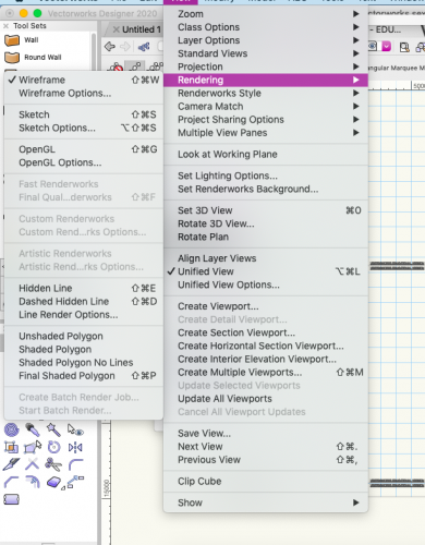
I'm writing an Python script with this part in it: vs.DoMenuTextByName('Standard Views',8) vs.DoMenuTextByName('Fit To Objects', 0) vs.SetLayerRenderMode(_hRenderlayer, 6, True, True) Now i have the problem that the script gives the order to set the view and zoom and VectorWorks will do this , but when the script is ordering to set the rendermode VW is still busy setting the zoom and view and will skip this step. If i run this script again without changing my zoom and view it will set the render mode correct because then VW can skip zoom and view and is ready when it gets the order to change the rendermode. I Think the issue is probably that VW is visually showing the zoom an view change and that takes time. To set the rendermode first is not working because it will change back to wireframe when the zoom/view is changed. I also tried the function vs.Wait() but this is not making any difference except the script takes longer to run. Has someone an idea to overcome this?
-
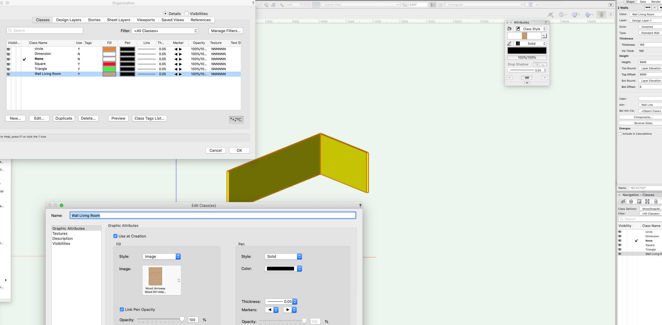
HI, I can't seem to apply a class (image) to a wall. I have no issue applying a solid colour but for some reason If I need to apply an image this does not work and defaults back to a colour. The wall is classed but I have no idea where the yellow comes from. I can render a wall with whatever image but when I apply class texture this does not work, even though the class is set (as it works with any color fills but not image fills). Photo attached. Anyone has any idea as this must be a simple thing which I did not grasp! Thank you,

-
Sometimes when you finish to elaborate a rendered viewport (maybe after hours) you need to manage the object for impagination setting. Not for rescaling picture, but for exemple you need to move it into the sheet layer, aling it, cut it, eccetera.. Try to move a rendered viewport and then press cntrl+z WIN or cmd+z macOSX. The rendered viewport disappeared, and it's easy not to take it positively. The same when you need to recover the backup file. All viewport are losts. So: could be very helpful to find something for really saving the rendered viewports, even when "saving cache viewport" is enabled. Maybe is just sufficient to create automatically a png image on the final process, like when you separate a pdf file, you know? Thank you and have good work Z
-
I've created a new file with walls. I attached radiators to some of the walls and in doing so, the properties of the walls change to HVAC equipment class. I've changed the walls back to be wall class and removed the radiators from the walls but my walls are all appearing in black in the GL render. How do I change this back? I've checked the class properties and they show the walls should be white but the walls remain black! Any suggestions?
-
Hello all, Hope this message finds you in good health most importantly. Really struggling today with a project where I have geometry rendering correctly in open GL but will not render correctly in hidden Line. Had a quick look through the forum and could not see this as an issue. Please see attached screen shots. The Open GL shows an extruded circle drawn onto some 3d geometry. When I render to sheet and set to hidden line I get an Octogon - rather than a circle. I've cut and pasted the geometry into a new file - same result. I've re-drawn the offending item several times - same result. New file, same result etc., The view port is set to High - but medium and low make no difference. the sheet dpi is currently 300 (up from the standard and again no change) Anyone had anything similar happen and and suggestions how to over come (i'm about to revert to doing 2d elevations and sections) many thanks all
.thumb.PNG.5a3c27ae6c48771b378102d24cf07fbf.PNG)
-
 I find it weird that we can't set a transparency shader to use the object attribute colour, would seem like a useful option.
 -
Glow Texture Brightness over 100 fix
Anthony Neary posted a question in Wishlist - Feature and Content Requests
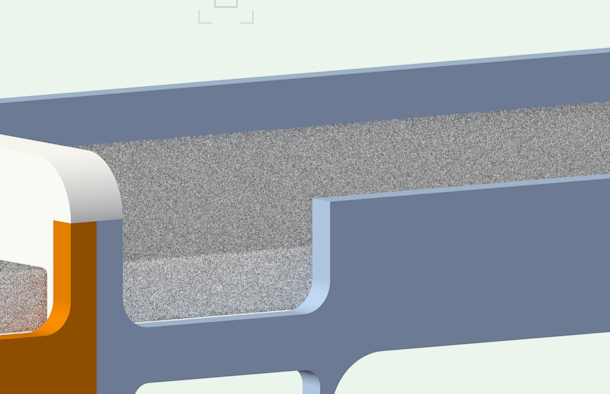
I would really like to see Glow Textures get "fixed" so that if you increase the brightness over 100 it doesn't 'over-expose' the colour to white (or give us an option either way). I'm trying to make my fixtures look like the fronts are glowing relatively realistically in renders, and re-balancing the entire drawing (camera exposure, other glow texture brightness, render light brightness, etc) around trying to make the lens glow texture flare as if you are looking at the fixture is a real pain in the ass. It would seem far easier to just be able to turn up the brightness on my lens glow texture without it washing the colour out to white when I do so. To me this seems like a simply fix.


.PNG.aaa947ea267f8df1d765d0c34e24cc0b.PNG)
.PNG.c1a37f4c18be543bafaf00bbead6fda6.PNG)
.PNG.017f3b267bb892861340f2d42961387f.PNG)