-
Posts
1,890 -
Joined
-
Last visited
Reputation
634 SpectacularPersonal Information
-
Occupation
Sales Enablement Director
-
Homepage
www.vectorworks.net
-
Hobbies
Vectorworks, Vectorworks and Vectorworks.
-
Location
United Kingdom
Recent Profile Visitors
The recent visitors block is disabled and is not being shown to other users.
-

Creating a viewport from design layers
Tamsin Slatter replied to Monique Freese's topic in Architecture
I like this method too - because you can see the other things on your sheet as you create the crop. -
Try the Site Modifier in Pathway mode. Here you can create any shape you like, with curves. The pathway has a longitudinal profile that can be modified to set precise elevations, You can also create as many transverse profiles as you like. The pathway starts out with a fixed width, but you can reshape as required, Once you’ve created your path modifier, add the hardscape and tell it to drape. Hope that helps.
-

a hardscape that mimics the existing site model surface
Tamsin Slatter replied to zhoukaiyi's topic in Site Design
No need to use Send to Surface. Just change the Site Modifer to Draped and it will fit the surface of the model. -

Site Model not Updating to Align with Hardscapes. VW 2024.
Tamsin Slatter replied to Jack2022's topic in Site Design
Apologies Jack - you always need to enclose modifiers with at least one grade limit. It's not a 1:1 relationship. It just sets the boundary for interpolation. The grade limit COULD be the whole site, or you could have several limits if you are making changes in several areas, but don't want to touch the land in between those areas. Maybe you want to protect the root zones of existing trees - areas outside a grade limit will not change. Areas inside the grade limit WILL change.- 20 replies
-
- hardscape
- hardscapes
-
(and 1 more)
Tagged with:
-

Grade Site Modifiers Not Working as Expected
Tamsin Slatter replied to Jack2022's topic in Site Design
Yes, add a Grade Limit - it CAN be around the whole site, or it can be around a specific area that is allowed to be regraded. -
The great thing about the Public Roadmap is that it's a direct line to the engineers and product planners.
-
Thanks @Poot. I have let our product planner know about this requirement. It might be a good idea to also request this on our public roadmap: https://www.vectorworks.net/en-US/public-roadmap
-
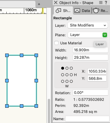
Not sure what the problem is. I've drawn a rectangle with the rectangle tool and here is the area, shown at the bottom of the Object Info palette:
-

Site Model not Updating to Align with Hardscapes. VW 2024.
Tamsin Slatter replied to Jack2022's topic in Site Design
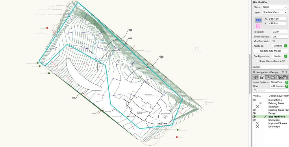
The Grade Limit determines the area that can be updated by site modifiers. You don't have to put one around every site modifier. But you would enclose an area that is to be updated. They enable you to prevent having to regrade the entire site when you are just making changes in one area. Here's a rough example. I've got the Grade Limit selected so you can see it clearly. So, any of this area will be updated by the addition of site modifiers (pads, grades), but the contours outside this area will be unaffected:- 20 replies
-
- hardscape
- hardscapes
-
(and 1 more)
Tagged with:
-
This might help. It's a few years old (like me), but don't let that put you off: https://university.vectorworks.net/mod/page/view.php?id=617
-
Apologies for the late reply. I'm not familiar with the datasets available to you in Denmark I'm afraid. In the UK I am able to get hold of free contour data from OS Openmap, but it involves downloading from the website and importing shapefiles. https://osdatahub.os.uk/downloads/open Although the shapefiles are 2D, I then use the Modify by Record command to Elevate the polys by their height value in the attached record. You can also use the same command on information that is linked through the Bind to Feature Service on a design layer.This will lose the connection to the original source data but that's no worse than downloading contours and importing them. I hope that helps.
-
I'm not sure... why you are not able to see it. See my note above about adding it to the workspace. The AI visualizer is processed on Vectorworks Cloud Services, and is available only with a subscription or as a benefit of an active Vectorworks Service Select agreement.
-
If you're up to date on the Cloud Services app, all is good with that and you won't see the Refresh button. Within Vectorworks, if you don't see it on the Model menu, you may be using a workspace that has saved itself in your user folder and is therefore considered a "custom" workspace. You can add the menu item yourself using Tools > Workspaces > Edit Current workspace. And you may also find it under the Windows > Palettes > Web palettes menu. Good luck!
-
Tamsin Slatter changed their profile photo
-

Site Model not Updating to Align with Hardscapes. VW 2024.
Tamsin Slatter replied to Jack2022's topic in Site Design
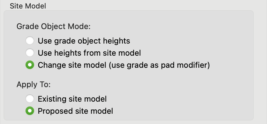
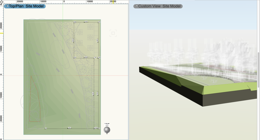
It should grade the area within if you create a completely closed set of grades. You need to make sure you choose the option to update the site model: And don't forget to enclose with a Grade Limit (mode from the Site Modifiers tool. Here's a screenshot of a small example file - on the Top/Plan view on the left you can see the connect grade objects that create the pathway up to a cafe area at the top right. On the 3D view, you can see the impact of those grades on the site, and you can also see where the draped hardscapes have excavated the site.- 20 replies
-
- 2
-

-
- hardscape
- hardscapes
-
(and 1 more)
Tagged with:


