
David S
-
Posts
347 -
Joined
-
Last visited
3 Followers


Recent Profile Visitors
2,753 profile views


-
Lost walls, all slabs, and roof in all rendering modes
David S replied to Dick Jenkins's topic in Architecture
I'm not sure this will help but we lost all our walls yesterday in 1 file only. (Not slabs and roofs tho) Turned out in View/class and layer options/ somehow the final settings had reverted to "active only" (not as it should be : show snap modify others. BUT we did have to shut the programme and file down for the issue to be rectified. This was directed by VW tech support in the States. Ally Wood. She was very helpful. This was tested in 2 files and corrected both times -
Gutted. Gonna have to re-release it after Christmas. So annoying!
-
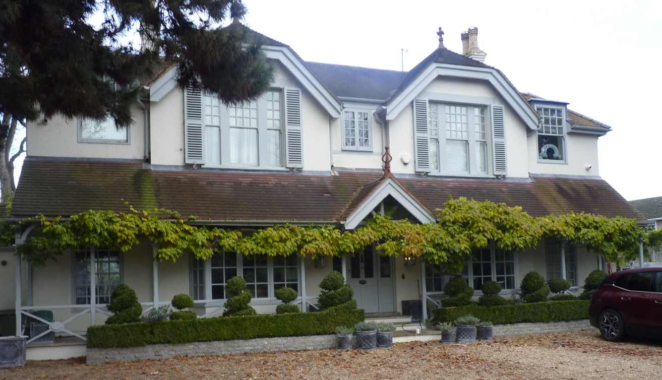
It's a survey. Not designed by us. It is what it is!
-
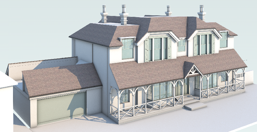
and then there's this one! But me and Vectorworks got there in the end! Enjoy and Have a great Christmas everyone! Cheers David

-
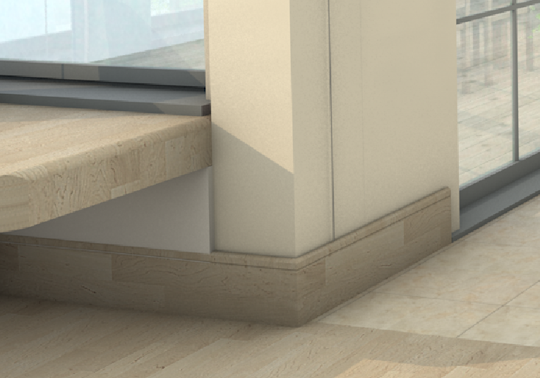
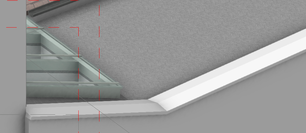
@line-weightine-weight EAP's Yes! I use them for parapets and even skirting. A bit tricky and illogical at times but a bit of perseverance and they are quite effective and strangely satisfying!
-
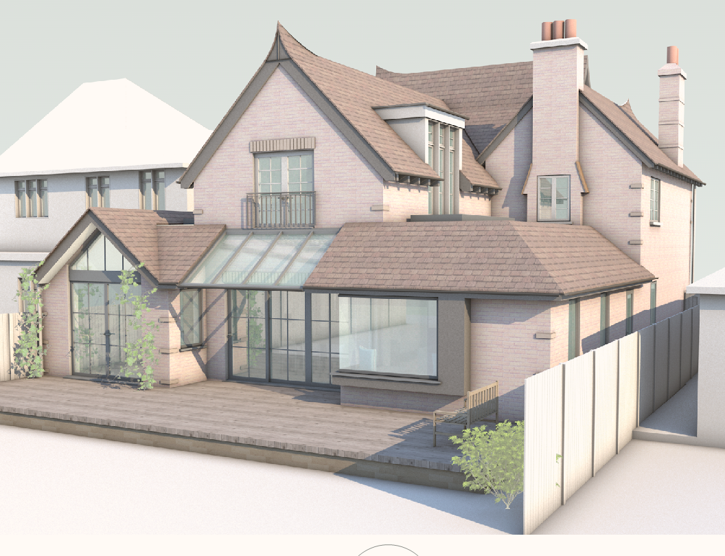
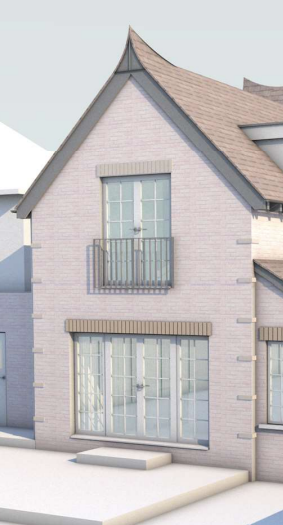
Well you did ask how the scheme would develop so here it is! My wife's design and a joy to create and render! @bcd you will notice I changed the 1st floor rear guard rail 😉

-
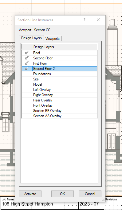
I've scanned this and it is touched upon but not explicitly I think. I was taught this by @Helen Law at VWUK and use it extensively now. Naming viewports allows you to link section viewports to design layers and viewports via section lines which appear automatically. Better still if you move the section line/s cut in the design layer they alter position automatically. More work up front but saves a lot of time in the long run. This can be activated by selecting your Section viewport(s), Going to the OI Pallette and clicking on section line instances (at bottom) within which you can nominate where you want the section lines to appear in both design layers and viewports. Cool!
-
Hi Todd that's very odd. I frequently use the FWTO tool and find it very useful and generally very user friendly. That said by nature of it's accuracy it is very also sensitive and as an aside I would observe several things:- If the accuracy of the roof (or whatever object/s it is being asked to join) is not near- perfect (ie a gap in the apex join) it will spot it! and the wall will stick out above the eg Apex. Fair play. On occasion it seems to "remember" previous nodes/points of the re-shaped walls and refuses to accurately re-shape itself. The fix is to "remove" these by deleting the top wall peaks and starting again. And finally it also gets confused if your new wall was 5000mm high and you need it re-shaped below eg 1800mm and it doesn't understand the instruction. Best to reduce the wall height to lower than the the lowest desired wall peak and this seems to fix the issue Hope this helps
-
STAIR visibility issue on Upper Layer floor plan viewport (HSVP)
David S replied to drelARCH's topic in General Discussion
@line-weight Gosh! Well if you are familiar, you will know stair accuracy/heights is really important for e.g. loft conversions to comply with building regs. I am a master-Vectorfudger! I gave up on the complicated stair tool a long time ago after a short and painful dalliance and reverted to the simple stair tool, which is what I use. Never had a problem with it. To compensate for its limitations I built my own ballustrades and Newel posts from extrudes and take great pleasure from applying them manually. Where there are more complicated 1st treads I also use manipulated floors. Winders the same. We hang our stairs from the upper floor downward. I might have a play around with this Hz cut, this afternoon...Business in the UK a bit tight currently due to projects being on hold. Suspect the interest rates are not helping! I also only downloaded 2023 to play around with the windoor tool (couldnt even work out how to add architraves) but also found it to be hugely complicated and quickly reverted to the native tools, and am still on 2021. I might also check out Jonathan Reeves 2024 video this afternoon. HtH. Cheers D -
STAIR visibility issue on Upper Layer floor plan viewport (HSVP)
David S replied to drelARCH's topic in General Discussion
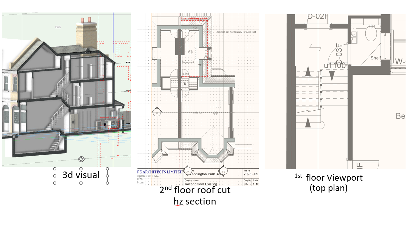
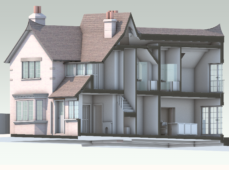
Hey All. What an interesting convo. We always use the Hz (Clip cube) generated section to display upper floors where the roof cuts in (middle diagram) but I had never considered Hz sections for displaying lower floors and have always used Top plan viewports. Must have a play around with this. I suppose the question is as has been discussed how to display the stair layouts in a trad Architectural stylee as diagram right. Are there any videos on this @Matt Panzer ? And yes before you ask, this was another very tricky survey being multi level on 2 floors! Cheers D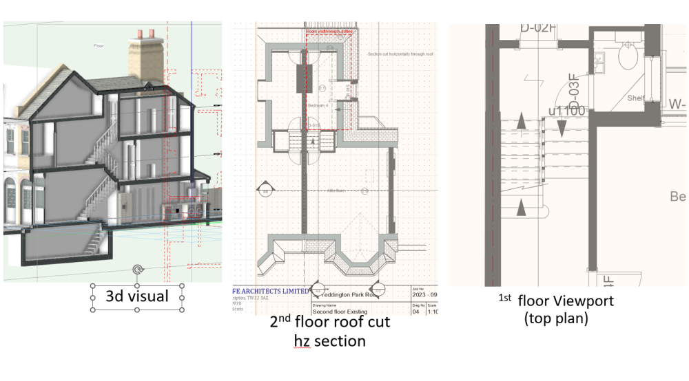
-
@Tom W. No we always do our own surveys and create a 3d model. That way we are sure whatever is designed complies with building regs. Had a few occasions when difficult builders say our designs don't work which is scary as by then the client has fallen in love with the builder but the 3d model never, never lies! The 3d model generates all the plans and sections etc. The aim is to extend to the rear.
-
@Tom W. What completely threw me on the survey was that on the ground floor rear where the stack is (behind the side extension) at some point they had inserted a door, now blocked off, so when I tapped the stack it was solid to the side but hollow-sounding in the centre and now housing a book case! And yes the first floor stack window is a feature!
-
@cberg I'm not sure I understand the question but it's all manually modelled. There's quite a few extrude along path objects like the chimneys and I really struggled with the pointy end roofs for a while before creating extrudes, subtracting solids and then converting to nurbs and manually manipulating the surfaces. It was an interesting build as its been quite heavily extended already, so for example you can see a legacy roof in the upper bathroom above the shower. It all made sense in the end!
-
Safety rail now added 🙂 @bcd
-
Good spot @Tom W. Must be fireproof Glass !