Matt Panzer
-
Posts
3,337 -
Joined
-
Last visited
Content Type
Profiles
Forums
Events
Articles
Marionette
Store
Everything posted by Matt Panzer
-
Are the section lines placed in design layers? If so, the best way to avoid this problem is to not show them in design layers, or place them on a design layer that's not visible in the viewports (if you want to have them there for reference). Then, select the section viewport and click on the "Section Line Instances" button in the Object Info palette. A dialog will appear allowing you to choose which layers and viewports to display the section lines in. Any viewports you show them in will place a section line in their annotations. Each section line marker will then display according to the scale of its parent viewport.
-
A bug is a behavior that is not intended by the software. It could be something that is barely noticeable, a crash, or anywhere in-between. My stating that we consider the behavior a bug was to let you know that it's not "by design" and needs to be fixed. The comment was not intended to lesson the severity of the problem - quite the contrary.
-
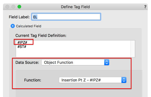
I believe the slab Height parameter is the same as its insertion point. Luckily, we do have a function for that and it does report in the current units. Try this: Spot Elev Try 2.vwx
-
No need for a file, @willofmaine. I created one for the bug report.
-
I try. 😉
-
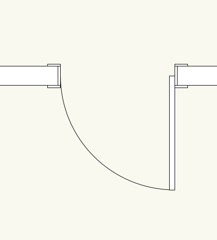
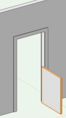
Hi @Christiaan, You're right about a lot of these problems regarding flipping and the object deciding what faces inside/outside from the wall. However, a door with a custom door leaf will always keep the same face of the door to outside, but it fails to keep one side of the door as a hinge side. As @TomKen mentioned, you can create vision panels without using a custom leaf - and that leaf flips as expected. The custom leaf should flip in the same way. I went ahead an entered a bug for this: VB-158845 @mike m oz, I agree with you about having real world options as this information may appear on schedules.
-
Ah, right. Thanks Kevin. I see the issue as well. @Christiaan, why do you feel this is by design? It looks like a bug to me.
-
@willofmaine, What version of Vectorworks are you seeing this in? Can you send me a file showing the issue
-
Probably the best way to create this would be to insert a door "Opening" of "Cased Opening", then insert another door at the same insertion point with the leaf dimensions you want and a Jamb With and Depth of zero.

-
You're very welcome. @Phileas ! BTW: The lack of highlighting of "valleys" outside the slab is a known bug. I gave that but a nudge. Hopefully we'll see those highlights in a future version so it can be more discoverable (and understood). We're also exploring ways to provide better control over control of sloping faces vs sloping valleys.
-
LOL! I believe this is the reason. If a slab is bound to walls, each segment contains bounding information. If you suddenly add more segments, you might get unexpected results. I have not confirmed this is the reason for sure, but I believe it is.
-
Hi @drelARCH, I received the file you sent me privately and the column rotation is a known bug. For now, the only workaround I can think of is to turn off "Display 2D Components" for the horizontal section viewport. This should give you results similar to that in Vectorworks 2018.
-
Yes. The boundary is the shape of the slab. Adding and subtracting surfaces create modifiers have the option to affect specific components of the slab, so they do not change the boundary.
-
Hi @drelARCH, Could you post (or send me privately) a file that shows the problem? There is a known bug similar to this and I want to make sure this is the same problem.
-
Hi Matt, I was able to reproduce the issue. However, the viewport does not appear to be destroyed. It displays at as if it were scaled by the viewport's scale. IOW: A 1:50 scale viewport will appear 50 times smaller on the sheet layer. Editing the viewport's annotations again will bounce it back to normal. I'll check to see if this is a known bug. If not, I'll submit one. Thanks, Matt VB-158610
-
Have you tried placing the garage walls and roof in classes that you can turn off in the other file? The reason the walls behave differently in symbols is because instances of the symbol can be placed on different layers, so walls in the symbol definition cannot be based on a layer, nor can it use story levels. If you insist on keeping them in the symbol, you can edit the wall components, make their tops/bottom bound to the wall (with offsets, if needed), then set the wall height via the Object Info palette. I still think you can get what you need using classes - which should be a lot easier.
-
Hi @Phileas, This can be done, but it's a little tricky and best explained in a video. Keep in mind that I talk about invisible valleys that are outside of the slab boundary. While they're not on the slab, they do effect how the sloped faces are calculated. HTH! -Matt Slab Drainage Challenge.mp4
-
 Right-click on the dimension you wish to add the note to and choose the "Edit Dimension" contextual menu command. An Object Properties dialog will appear for the single dimension within the chain. While the interface is not ideal, it will give you what you need.
 -
Display scale of 'Page-based Symbol' all over the shop
Matt Panzer replied to Amorphous - Julian's question in Troubleshooting
This is a known issue related to the Navigation Graphics “Best Perfomance” setting. Changing it to another setting should fix it for now. This should be addressed in an upcoming service pack.- 1 reply
-
- 1
-

-
- symbol
- page based
- (and 3 more)
-
Section viewport: inconsistent behaviour
Matt Panzer replied to line-weight's question in Troubleshooting
I hear you. My point is that we have been, and will continue, improving section viewports. The bug you state in this thread would be considered minor (IMO) for the reasons I stated earlier. The other bug you mentioned, however, is more serious and I stated as such in the report I submitted. -
Section viewport: inconsistent behaviour
Matt Panzer replied to line-weight's question in Troubleshooting
Given the improvements added to vertical and horizontal sections in VW 2019, I hope it's evident that we feel the same. 🙂 -
Why is object appearing in wrong position in section VP?
Matt Panzer replied to line-weight's question in Troubleshooting
No problem! I just submitted the bug. BTW: This problem also effects regular viewports rendered in hidden line. Wireframe is unaffected... -
Why is object appearing in wrong position in section VP?
Matt Panzer replied to line-weight's question in Troubleshooting
Hi @line-weight, I played around with this and also see the problem. Here are a few things I noticed: In Vectorworks 2018, the further out your zoom level, the larger the displacement of the objects when updating the viewport. The displacement is much less in Vectorworks 2019 and the zoom level has no effect. I'll submit a bug with your file. -
Section viewport: inconsistent behaviour
Matt Panzer replied to line-weight's question in Troubleshooting
Right. I certainly understand the frustration. I wish I had an answer of why it's not consistent. As we continue to improve our section viewports, we do want to eliminate these inconsistencies whenever possible. Yes. I saw that post and did investigate a bit. I'll add a comment to the thread. -
Section viewport: inconsistent behaviour
Matt Panzer replied to line-weight's question in Troubleshooting
The problem is that the geometry beyond is rendering and the line of the one extrude beyond is showing along with the cut line. While sections try to be smart about which lines beyond to hide, sometimes they show. This is usually not a problem because the cut is typically a thicker solid line than the line of objects beyond. What you have is a sort of 3D annotation object being sectioned as part of the model. While I completely understand why you want to do this, there are conflicts between how the model should be sectioned and how an annotation is drawn. For example: If the 3d sectioned "annotation" happened to be drawn on top of parts of the actual model (eg: top of a slab), you would want that line beyond drawn. Sections do not know that you want particular objects to be treated differently. What we really need is a built in way to have 3D grids so viewports will know what to do with them.