Phileas
-
Posts
206 -
Joined
-
Last visited
-
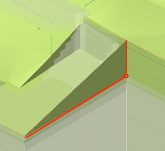
@amcdonell Your problem can be solved by creating a new vertex to the retaining edge and placing it here: Keep in mind you terrain will follow the retaining edge, so if it runs up diagonal like in your pic, the site model will create this "fillet" to match it. Double-click on the retaining edge in a 3D view and add a vertex to the retaining where I placed the red circle to solve your problem. The site will then follow the red line I drew.
-
@Hans-Olav tried it with this, and was only half happy with the result, so I drew over them 😉
-
@Hans-Olav Thanks for your help man I've played around a little with the options I have, and came out with this: I like the design like this, I'm really happy with it 🙂 I drew above the site model with polys to get rid of the triangulation of the 3D polys making the mesh, and drew polys with a "Shadow" class above the shadows of the openGL model with 600DPI to get vectors (polygons/polylines) as shadows instead of pixelated ones 🙂
-
@Hans-Olav that's the method I used to find out all my stairs had a weird 3D loci associated to them at around 2e98 Z value... Any idea how this could have happened?
-
@Hans-Olav no problem thx mate. I figured out I had a few objects with infinite XY coordinates, and rebuilt those. Now it seems to work fine.
-
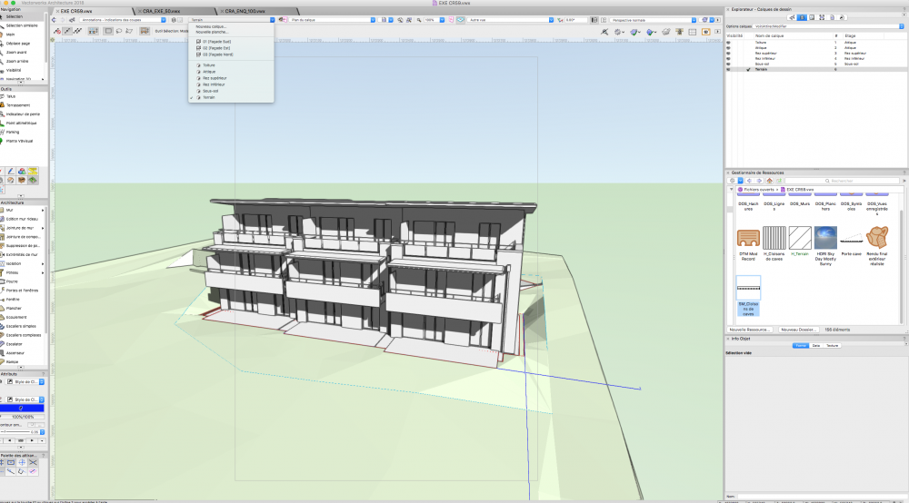
@Hans-Olav Exactly what I did. Except you can't have openGL as the background render (the option doesn't show in my OIP, only hidden lines is possible). So I have OpenGL as the front and hidden lines as the background render. I'll show you my problem: here's the setup you described. You'll quickly notice there are no shadows showing and no other openGL components like colour either. I't just a plain hidden line render, despite OpenGL beeing the front render. VP Setup.mov I skipped the VP update, here's a screenshot of the end result: no shadows, no colour, just hidden lines. Something's obviously wrong with OpenGL. weird behaviour of openGL.mov watch this and if you understand anything of what is going on please help me. I just don't get it. All my viewports behave like this. File in Attachement: EXE CR59.vwx
-
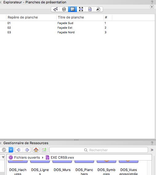
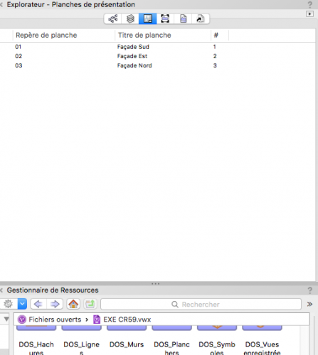
@Hans-Olav yeah I created this "presentation sheet" (or however it is called in english), gave it A2 dimensions and a 300DPI resolution, and created the viewport on that sheet. I didn't create a design layer if that answers your question. Google tells me this is called a sheet layer in english. That's just the standard way of creating viewports isn't it?
-
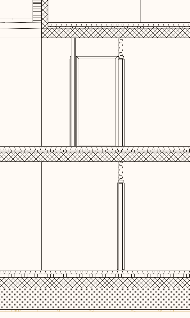
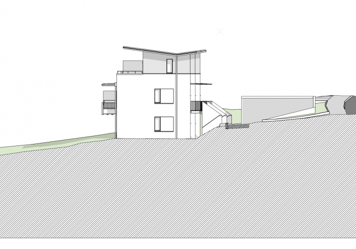
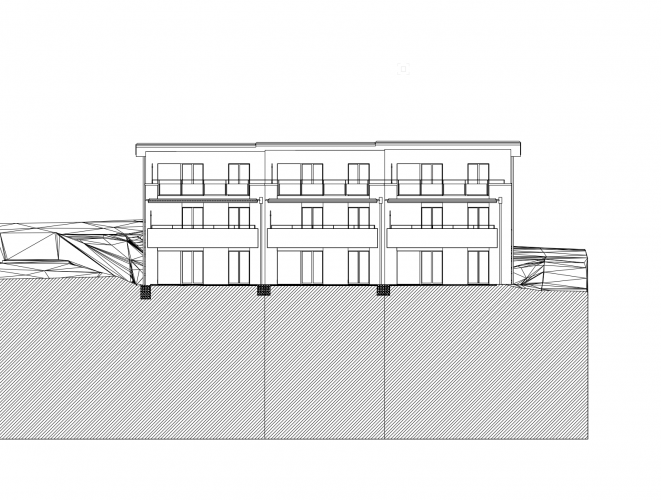
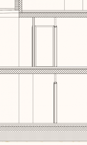
Hey guys I'm trying to render an exterior elevation of a building I've modeled. I'd like to use OpenGL as a main rendering mode so I can display shadows and colours for the site model, and Hidden lines as a secondary rendering mode to emphasize the linework. However, whenever I change the main rendering mode to OpenGL, the building disappears and only the site model remains. when I hover over the building's location with the selection tool, some geometry outlines in grey and I get points to snap to, so the building is obviously still there, it simply doesn't show. Layer and class visibilities are all absolutely normal, and when I enter the viewports by double-clicking and choosing "edit objects in section" (I make my exterior elevations using sections at the bottom end of the wall), the building reappears and shows normally. Exiting back to the Viewport deletes it again. Has anyone experienced similar issues?
-
Walls with wall styles in symbols can't have lineweight?
Phileas replied to Phileas's topic in Architecture
@Wes Gardner thanks for your answer. I can't open the file since I'm still on VW2018, but what you describe seems to be what I'm looking for. Yes all my walls are defined by wall styles, and the components of these styles are defined by class, so everything should be editable by class. However, everything should be working, the class my walls are assigned to has a correct lineweight, the wall components are in the right class, the wall object is in the right class as well, but the lineweight can't be changed from 0.00... Are the walls in your file defined not only by class but also have a style? Because I have further up in my file a set of walls in symbols that have no wall style, and these can be adjusted without a problem. -
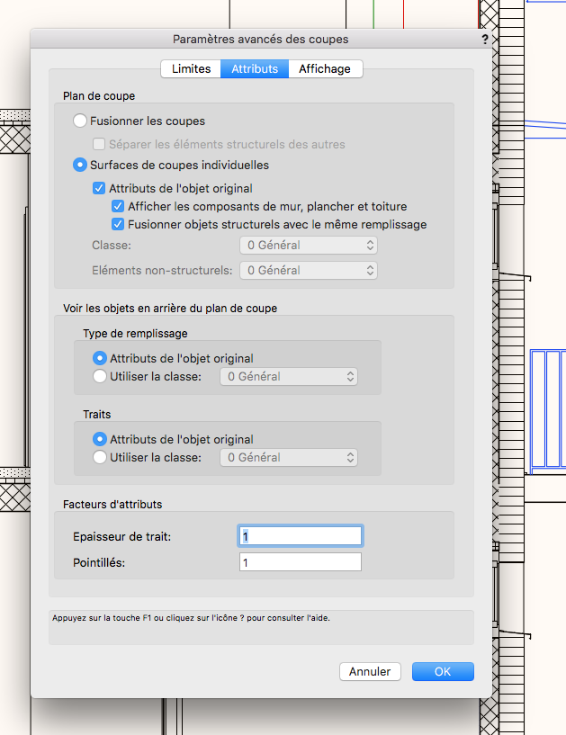
Hey guys I have problem with something kinda annoying: I have 3 appartment blocks that are exactly the same from the interior walls, so I modeled them putting the walls inside a symbol. The components of these walls are defined by wall style. I don't understand why, but in the attributes pallette, everything is greyed out except lineweight, and this lineweight is set to be 0.00 . And it is impossible to change it, it automatically reverts back to 0.00 . Wall Lineweight 1.mov I supposed this is linked to the wall being inside a symbol, but using the same wall style on walls outside the symbol resulted in the same problem. I then checked all my walls since all of them are defined by wall style, and noticed that all of them are like this. So this is normal (?). The problem with that is that I have no way to define the lineweight. And this is a problem in section VPs: the walls appear without a lineweight. Now I guess this is also the source of some other problems I've been meeting: I my sections VPs, some lines on walls just randomly stop for no reason. Viewport problem.mov here's the advanced properties tab of the VP, I don't think I got this one wrong (?). Is this all by design and I'm missing something? I would be really disappointed that after modeling an entire building in 3D the automatic sections don't work as planned...

-
@Alan Woodwell oooh yeah grade limits could be my saviour here!! thanks for the idea, will definitely try out!
-
@Benson Shaw yeah something appears to be wrong, I simply can't figure out what... I already have everything surrounded with a grade limit, and yes it solved some issues, but some appear to be just generated by bugs... I moved one vertex of a problematic pad 5cm on the x axis, then moved it back to it exact starting position, updated the model, and the problem was gone lol. @Alan Woodwell I already replaced every pad I could with normal ones, but I need a retaining edge for at least a few, so no real solution there. Right now I'm simply hoping all the bugs will somehow disappear.
-
OK update: The site model created with only 3D points still shows the same problems, so I guess my site modifiers are causing the issue. However, there are no site modifiers intersecting, the site model is reporting no problems. I'm running out of ideas...
-
Kinda talking to myself here I'm starting to think that my site model somehow ended up being corrupted or idk... When I try to rebuild it from the source data by double-clicking the site model, there is no data inside it... And when I exit the model, it disappears completely, deleted forever... luckily CMD+Z exists lol. I've got a separate file with a clean copy of the original site model. This one is still fine, but it says there are errors in the source data (3D polys), saying 3D polys are intersecting. It then marks every point where 3D polys converge as a problematic intersection in the source data. Maybe that could be the problem? I'll try and replace the 3D polys with 3D points at the correct height at every intersecton, and update you guys with the result. btw, inserting the site model from my backup file into my current problem file, replacing the corrupt model and updating the new site model to show the site modifiers in place still ends up with the same problem, so no solution there.
-
I feel like either I'm using this tool wrong, or it's just not finished properly and full of bugs... here's another example: no pads intersecting, no errors, nothing, and I get this result on pads that aren't remotely related to the one I'm modifying... Pad Problem.mov