markdd
-
Posts
3,419 -
Joined
-
Last visited
Content Type
Profiles
Forums
Events
Articles
Marionette
Store
Everything posted by markdd
-
Experienced designer, very, very new to Vectorworks
markdd replied to Iainy1961's topic in General Discussion
Your question has many possible answers! Can you post an image showing what the problem is? -
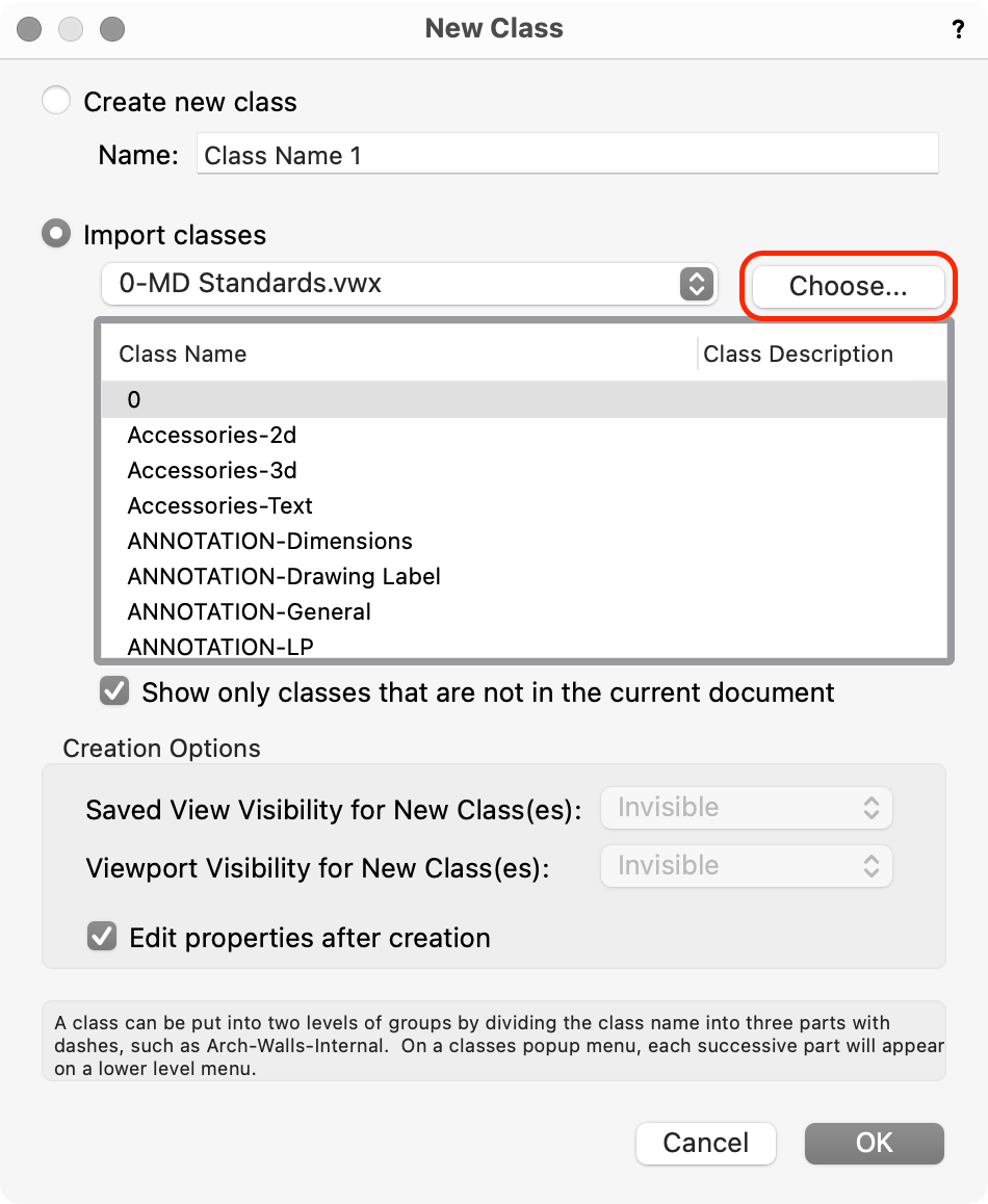
When you create a new class, click on the Import classes button. This will open this dialog. Choose Import Classes and then click on the Choose button to navigate to the file you want to import the class from. Select the class that you want and all the parameters and attributes shoul be imported into the file in one action.
-
Personal Libraries in diferent computers
markdd replied to Cristiano Alves's topic in General Discussion
Personally, I have a workgroup set up in a cloud drive like Dropbox or Google drive. I then add them in using the Workgroup functions in Vectorworks preferences. You can export/update any resource using the resource manager and the changes will be migrated to all machines. -
Label Legend Not Behaving as Expected
markdd replied to SharpToShutter's question in Troubleshooting
As Kevin suggested, the Container symbols are not centered on their origins. Go to the Containers folder in the Resource manager and edit each container symbol so that the geometry is centered around the insertion point. That instantly solves the problem. -
I think it is being revised. It can be enabled from Document preferences under the Legacy Tab.
-
Label Legend Not Behaving as Expected
markdd replied to SharpToShutter's question in Troubleshooting
It’s worth saying that the placement of the containers in the Label Legend symbol is only a guide to help with text spacing. The insertion points of container symbols are always aligned the insertion point of the text block in the final Label legend when it is assigned to a lighting device. -
Label Legend Not Behaving as Expected
markdd replied to SharpToShutter's question in Troubleshooting
If you put the label legend into a file and post it here I’ll try and troubleshoot it for you….. -
Unless I am very much mistaken, then that is the case. I know that when I transferred to a full licence a few years ago, then the Stories Tab appeared in the Organisation dialog.
-
Do you have a Designer licence? Stories aren’t included with the Spotlight package.
-
Sorry, I have confused things. My mistake. I meant Set Working Plane rather than Select. (There are too many distractions here at the moment.) The cmd + \ shortcut activates the Set Working Plane menu command which I have in my Working Plane menu Commands list. I use this in conjunction with the Automatic Working Plane functionality as per the video.
-
No, it is a dedicated shortcut to just use the second mode of the Set Working Plane Tool. Set Working Plane.mov It's incredibly useful as you can use the shortcut when you have a surface highlighted when in Automatic Working Plane and it can run at the same time as say a tool command, meaning that you can hold a working plane that you have already set using the Automatic Mode. Set Working Plane 2.mov
-
I know this probably won’t help you now, but I opened the file in 2023 and all is fine. Have you tried converting any sweeps and other problematic objects into Generic solids?
-
Wall Tool Eye Dropper
markdd replied to _James's question in Wishlist - Feature and Content Requests
Have you tried the Create Similar Object command/tool? Option+Command (PC: Ctrl+Alt) - The cursor will change to a pipette. Click on the wall style you want to activate and the Wall tool will be activated with the correct wall style loaded. The Command is also loacated in the Workspace editor, so you can add it to a Menu and assign another shortcut to it of you prefer.... -
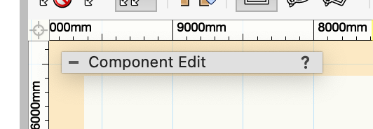
Is there a way to loose the component edit pop-up thing?
markdd replied to Kaare Baekgaard's question in Troubleshooting
I do all the time….. -
Hi Kevin 2d components is there for lighting devices, just about, but it doesn’t work with accessories yet. I filed a bug a while back about that so let’s hope there is a little more development soon. there is so much that one would want to do with non-horizontal lighting that I actually think that Schematic Views need more customisable options rather than the rather cursory dialog that is offered when thay are made. I wish Vectorworks would reach out a little more on this topic as I suspect it wasn’t anticipated that their usefulness would be quite as broad as it has become.
-
What view are you asking the SV to display? You need to ask the SV to display the component of the Symbol you want to see and not the view of it in 3D. Have you seen this video I made - couple of years ago? If you are still having problems come back.
-
@Bill McGarvinBut the light is still passing through though the solid objects, no?
-
1. Have you enabled cast shadows for the individual lighting devices? 2. I have seen this problem with another user’s file. Is all the geometry native to Vectorworks or is the solid geometry of the drapes imported from elsewhere?
-
If you look at the Symbol in the first image, you will see that it is offset from the Insertion point which is indicated by the X and y axes. It must have got moved somehow. Hopefully by adjusting all the Label legend content to X=0 you should sort out the problem.
-
Scale Bar text control
markdd replied to TessF's question in Wishlist - Feature and Content Requests
Watts is another one. Should be shown as “W”, VectorWorks displays it as “w”.- 1 reply
-
- 1
-

-
Cutting a Generic Solid with Split Tool Seems inconsistent
markdd replied to stayathomedad's topic in General Discussion
I'm getting the same result as you. Sometimes this happen. I will report it as a bug. As a workaround though you could draw an extruded line to create a Surface and then use the Surface with the Section Solids command which works absolutely fine. (This is essentially what the Split Tool is doing anyway) Hope that helps. -
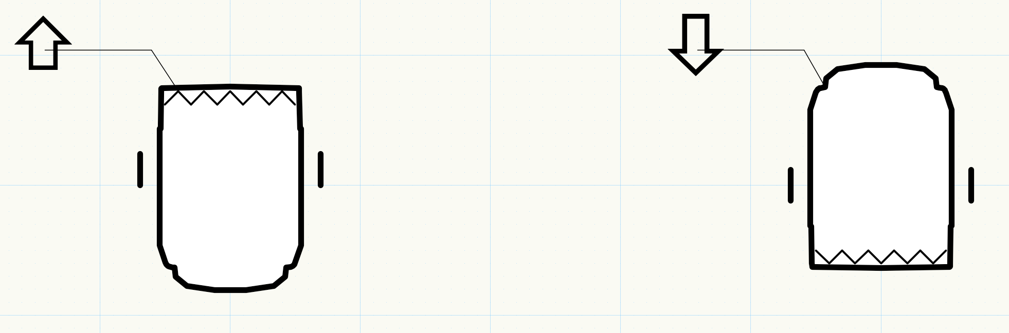
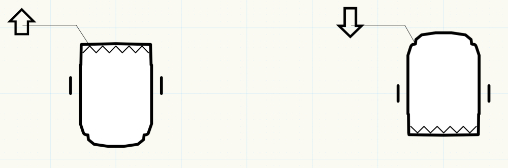
I would like to create a Data Tag that shows an Arrow in 1 of four different directions. I am aware that IF statements are available in Data Tags and so far I have come up with this String that will do what you see in the image below. ⇧@#Lighting Device#.#Pan#<90:⇩ However, I have drawn a blank when it comes to creating ranges of values. For instance I would like an: Up Arrow when Pan angle is between 45 and -45 Left Arrow when Pan angle is between 45 and 135 DOWN Arrow when Pan angle is between 135 and 225 RIGHT Arrow when the Pan angle is between 225 and 315 I have figured out that I will possibly need 4 text blocks in the Data Tag but ulimately it would be great to learn how to create this string with one Text block if possible. Any help with this conundrum would be greatly appreciated. As a sidebar, I have noticed that the Greater than ">" and Less than"<" math symbols seem to be behaving the wrong way around in Data Tags. This is probably my stupidity, but it certainly tripped me up while doing this..... Direction Data Tags.vwx
-
As @Kevin Allen said, the point of Layer Scale is to give you an accurate view of how your work will look when printed to a particular scale. Crucial to this is how you see the view in front of you with reference to the zoom value in the View Bar. if you select 100%, then that is exactly how the printed output will look to all your collaborators - Take a scale ruler and measure the geometry on your screen. It works - Pen thickness, Linetypes Hatches and all.... Even Text which you can enter at values that most people can relate to such as 12pt which most people know they can read with no problems. My understanding has always been that it helps you design efficiently so that when you output to Viewports and Sheet Layers there are no nasty surprises. What many people don't realise is that Vectorworks is not scaling the geometry and is actually drawing at 1:1, its just that it is showing you what the geometry will look like when printed to scale. You can also print at a particular scale from a Design Layer and the Page Boundary tool is very useful for this. This makes it really easy to print off or generate pdf's to quickly send to colleagues during a design process without having to go through the steps involved with Viewports and Sheet Layers. Problems come for many people when they import drawings from AutCAD which have crazy Pen Thicknesses which then look way too thick when viewed at a particular design Layer Scale. As long as you know this phenomenon exists then it is easily possible to scale the pen thickness in the Viewports, or change them to something suitable using classing in the usual way. Hope that helps. Im sure other folk will add to this!
-
Is there a way to loose the component edit pop-up thing?
markdd replied to Kaare Baekgaard's question in Troubleshooting
I don't think so, but you can make it very small.... And then even smaller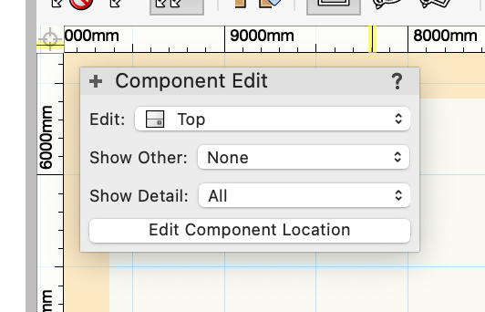
-
Matching document coordinates across multiple drawings
markdd replied to Jack2022's topic in Architecture
You can define a user origin. Menu>Tools>Origin. If you know the precise coordinates then this may be the solution.